AD8220-EVALZ Analog Devices Inc, AD8220-EVALZ Datasheet - Page 2
AD8220-EVALZ
Manufacturer Part Number
AD8220-EVALZ
Description
BOARD EVAL FOR AD8220ARMZ
Manufacturer
Analog Devices Inc
Specifications of AD8220-EVALZ
Design Resources
Fully Isolated Input Module Based on AD7793, ADuM5401, and a High Performance In-Amp (CN0067)
Channels Per Ic
1 - Single
Amplifier Type
Instrumentation
Output Type
Single-Ended, Rail-to-Rail
Slew Rate
2 V/µs
-3db Bandwidth
1.5MHz
Current - Output / Channel
15mA
Operating Temperature
-40°C ~ 85°C
Current - Supply (main Ic)
750µA
Voltage - Supply, Single/dual (±)
4.5 V ~ 36 V, ±2.25 V ~ 18 V
Board Type
Fully Populated
Utilized Ic / Part
AD8220
Silicon Manufacturer
Analog Devices
Application Sub Type
JFET Input Instrumentation Amplifier
Kit Application Type
Amplifier
Silicon Core Number
AD8220
Kit Contents
Board
Lead Free Status / RoHS Status
Lead free / RoHS Compliant
Other names
AD8220-EVAL
AD8220-EVAL
AD8220-EVAL


AD8220-EVAL
INPUT
The AD8220 requires a small amount of current, I
input transistors to function properly. Inputs should not be left
floating. If they are floating, such as when the inputs are
connected to a transformer, thermocouple, or a pair of series
capacitors, they should have a dc path to ground, as shown in
Figure 4
current path from the signal generator to the input, the circuit
in
generator and the input. The series capacitors prevent a dc
current from flowing into the instrumentation amplifier’s input
transistors. Matched 10 kΩ resistors are used between the
instrumentation amplifier’s inputs and ground to provide the
necessary current path. Resistors should be matched to reduce
offset and CMRR error.
ESD CAUTION
ESD (electrostatic discharge) sensitive device. Electrostatic charges as high as 4000 V readily accumulate on the
human body and test equipment and can discharge without detection. Although the AD8220-EVAL features
proprietary ESD protection circuitry, permanent damage may occur on devices subjected to high energy
electrostatic discharges. Therefore, proper ESD precautions are recommended to avoid performance
degradation or loss of functionality.
ORDERING GUIDE
Model
AD8220-EVAL
©2006 Analog Devices, Inc. All rights reserved. Trademarks and
registered trademarks are the property of their respective owners.
500mV p-p,
Figure 4
10V p-p,
100Hz
10Hz
. In contrast to the circuit in
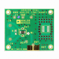
Figure 3. Example of Evaluation Board Configuration
has series capacitors, C1 and C2, between the signal
+IN
–IN
10µF
5.49kΩ
0.1µF
R1
+15V
+
–
AD8220
DUT
+V
–V
S
S
W1
Figure 3
–15V
0.1µF
EB05951-0-3/06(0)
OUT
REF
, which has a
10µF
B
OSCILLOSCOPE
, for the
B
T
Description
Evaluation Board
+ COM
Rev. 0 | Page 2 of 2
OUTPUT
Output measurements should be made by measuring the
voltage across OUT and REF, as shown in Figure 3 or Figure 4.
If an external voltage reference is used, the output can be
measured as shown in Figure 2. The evaluation board offers an
SMA/SMB outline. By default, the output voltage measured,
using an SMA/SMB connector, is with respect to GND.
Figure 4. Providing a Bias Current Path to the Inputs of the AD8220
C1
C2
+IN
–IN
10kΩ
10µF
10kΩ
499Ω
0.1µF
R1
+15V
+
–
AD8220
DUT
+V
–V
S
S
W1
–15V
0.1µF
OUT
REF
10µF
OSCILLOSCOPE
+ COM
T T T
Related parts for AD8220-EVALZ
Image
Part Number
Description
Manufacturer
Datasheet
Request
R

Part Number:
Description:
AD8220/1/6/8/9 MSOP Pkg Eval Bd
Manufacturer:
Analog Devices Inc
Datasheet:

Part Number:
Description:
Single Supply, Rail to Rail Low Power FET-Input Op Amp
Manufacturer:
Analog Devices
Datasheet:

Part Number:
Description:
±1.7g Dual-Axis IMEMS Accelerometer Evaluation Board
Manufacturer:
Analog Devices Inc
Datasheet:
Part Number:
Description:
Inertial Sensor Evaluation System
Manufacturer:
Analog Devices Inc
Datasheet:
Part Number:
Description:
Manufacturer:
Analog Devices Inc
Datasheet:
Part Number:
Description:
Manufacturer:
Analog Devices Inc
Datasheet:
Part Number:
Description:
Manufacturer:
Analog Devices Inc
Datasheet:
Part Number:
Description:
Manufacturer:
Analog Devices Inc
Datasheet:
Part Number:
Description:
Manufacturer:
Analog Devices Inc
Datasheet:
Part Number:
Description:
Manufacturer:
Analog Devices Inc
Datasheet:
Part Number:
Description:
Manufacturer:
Analog Devices Inc
Datasheet:
Part Number:
Description:
Manufacturer:
Analog Devices Inc
Datasheet:
Part Number:
Description:
Manufacturer:
Analog Devices Inc
Datasheet: