ADNK-3061 Avago Technologies US Inc., ADNK-3061 Datasheet
ADNK-3061
Specifications of ADNK-3061


Related parts for ADNK-3061


ADNK-3061 Summary of contents
Page 1
... ADNK-3061 Optical Mouse Designer’s Kit Design Guide Introduction This design guide describes how a cost-effective combi- nation USB-PS/2 yet feature-rich optical mouse can be built using the Avago Technologies high performance ADNS-3060 optical mouse sensor and Cypress Semi- conductor CY7C63743-PC USB microcontroller. The ...
Page 2
Mouse Optics The of Z-wheel motion is detected using the traditional method by decoding the quadrature signal generated by optical encoder. Two phototransistors are connected in a sourcefollower configuration. An infrared LED shines, causing the phototran-sistors to turn on. In ...
Page 3
... USB peripheral attached. These connections are shown in Figure 3 below. ADNK-3061 Designer’s Kit - Optical Mouse The ADNK-3061 optical mouse unit allows users to evaluate the performance of the Avago’s Optical Tracking Engine (sensor, lens, LED assembly clip, LED) over both a USB ...
Page 4
... USB cable. (See Figure 4.) Unscrewing the one screw located at the base of the unit can open the ADNK-3061 unit. Lifting and pulling the PCB out of the base plate can further dis- assemble the mouse unit. ...
Page 5
... Reference Design Documentation – Gerber File EFT tests when The Gerber File presents detailed schematics used in ADNK-3061 in PCB layout form. See Appendix C for more details. Overall circuit A schematic of the overall circuit is shown in Appendix A of this document. Appendix B lists the bill of materials. ...
Page 6
Enumeration The host initiates SETUP transactions that reveal general and device specific information about the mouse. When the description is received, the host assigns a new and unique USB address to the mouse. The mouse begins to respond, communicating ...
Page 7
USB Firmware Description A function call map for USB operation is shown in Figure 6. Following are descriptions of the functions in adns-3060. asm. USB Main USB Initialization USBTaskLoop ProcessButtons ProcessOptics Load new mouse packet to EP1 buffer & enable ...
Page 8
Dual USB and PS2 Functions GetMouseType – called in dualMain when the mouse is first plugged into the PC. This routine returns the interface of the mouse. The following sequences are performed by the micro-controller to determine the mouse type. ...
Page 9
USB Functions usbMain – This routine initializes the USB related parame- ters and enables VREG to signal the host that the mouse has been connected. The program then goes to the us- bTaskLoop . usbTaskLoop – This function spins in ...
Page 10
PS/2 Firmware Description A function call map for PS/2 operation is shown in Figure 7. The following are descriptions of the functions in Adns- 3060.asm ps2SendNextByte ProcessOptics PS2DoCommand HostRequestToSend ReadMotionReg PS2HostINhibit ReadDeltaX PS2Send ReadDeltaY Read Z Wheel Send_1 Send_0 Figure ...
Page 11
PS/2 Functions PS2Main – Initializes the PS/2 related parameter to their default state, enables the serial interface and sends a BAT code (AAh followed by 00h) to the host. After the initialization, the program goes into the infinite PS2TaskLoop loop. ...
Page 12
Interrupt Service Routines (ISR) The CY7C63743-PC features 12 different sources of inter- rupts. There are only four ISRs implemented in this appli- cation interrupt is enabled and the conditions for the interrupts are met, the microcontroller will generate ...
Page 13
... Vcc QB P1.5 240Ω 7 P1.4 Z LED XTALOUT XTALIN 13 6 MHz (Optional) Figure A1. Circuit-level block diagram for ADNK-3061 designer’s kit optical mouse using the Avago ADNS-3060 optical mouse sensor and Cy- press CY7C63743-PC enCoRe USB Controller. 13 LP2950ACZ-3 Vin Vo GND 0.1 F 4 ...
Page 14
Appendix B: Bill of Materials for Components Shown on Schematic Part Type 0R (Jumper) 0R (Jumper) Ceramic cap. 0.1uF (104) Chip resistor 10K 1% Resistor 187R 1% 0.125W Chip resistor 1K 1% Chip resistor 1K3 1% Chip resistor 20K 1% ...
Page 15
Appendix C: PCB Layout Figure C1. PCB Schematic (Bottom Layer). Figure C2. PCB Schematic (Top Overlay). 15 ...
Page 16
Figure C3. PCB Schematic (Bottom Overlay). 16 ...
Page 17
Appendix D: Base Plate Feature Figure D1. Bottom, top and side view of base plate. Figure D2. Overall top view of base plate. Appendix E: Sectional View of PCB Assembly Clip Sensor Lens/Light Pipe Base Plate Surface Figure E1. Sectional ...
Page 18
Appendix F: USB data reporting format The USB report has two formats, depending whether boot or report protocol is enabled. The following format is the boot protocol, and is understood by a USB aware BIOS. Bit 7 Byte 0 0 ...
Page 19
The PS/2 specification calls out the following default mouse report format. Byte 0 is the button data (1=pressed, 0=released), X and Y optics sign bits, and X and Y overflow bits. Byte 1 is the X optics data in 2’s ...
Page 20
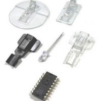
... LED Assembly Clip (Black Clip) ADNS-2220-001 LED Assembly Clip (Transparent) HLMP-ED80-XX000 639 mm) Diameter LED ADNK-3061 CD Includes Documentation and Support Files for ADNK-3061 and CY7C63743-PC Documentation a. ADNS-3060 Data Sheet b. CY7C63743-PC Data Sheet c. ADNS-2120 Data Sheet d. ADNS-2220 Data Sheet e. HLMP-ED80-XX000 LED Data Sheet f. AN 5035 – ...