HDJD-JD02 Avago Technologies US Inc., HDJD-JD02 Datasheet
HDJD-JD02
Specifications of HDJD-JD02


Related parts for HDJD-JD02


HDJD-JD02 Summary of contents
Page 1
... Avago HDJD-JD02 Development Kit ICM Program User Guide WARNING: This product is non RoHS compliant ...
Page 2
... WITHOUT GALVANIC ISOLATION. DO NOT CONNECT OR DISCONNECT ANYTHING WHILE THE HDJD- JD02 DEVELOPMENT KIT OR THE PC IS SWITCHED ON!!! Doing so anyway may damage your PC and/or the HDJD-JD02 Development Kit permanently. Make sure power is off while interfacing with the Color Reader Board. DO NOT & never switch off power from color reader board while program is running ...
Page 3
Introduction Being able to accurately and consistently ‘name’ a color, the Avago color sensor opens up opportunities to manipulate and control color ideal for color detection, differentiation and control in both open and closed loop systems. Potential ...
Page 4
Startup Included in Delivery Standard Avago Sensor Development Kit includes the following components: • One sensor module – Reflective Sensor Kit (RSK) • One sensor module – Transmissive Sensor Kit (TSK) • One A/D board – Color Reader Board ...
Page 5
... Reflective color sensing kit comprises an illuminant, color sensor and post filtering circuitry. The Avago white phosphor LED is used as the illuminant/light source and Avago’s color sensor (HDJD-S722-QR999) as the detector. Optical lens is also added to focus reflected light onto the color sensor.The kit also features an alignment gauge for maintaining an optimum gap between sensor and the targeted surface ...
Page 6
Reflective Color Sensing Theory of Operation Figure 3.1 Schematic of reflective color sensor Reflective Sensing Kit (RSK). By definition of reflective sensing, the color sensor detects light reflected from a surface or an object. The sensor module is designed in ...
Page 7
Transmissive Color Sensing Theory of Operation Figure 3.3 Schematic of Transmissive Sensing Kit (TSK). By transmissive, it means the application kit is placed facing the light source being measured. The filter- coated photodiode array of the color sensor converts the ...
Page 8
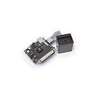
Analog to Digital Converter Board The Analog to digital converter board comprises of the following components: (1) Avago color controller (2) Line/power supply filtering circuit (3) USB power supply connector (4) Parallel port connector (5) Resistors and capacitors As the ...
Page 9
Hardware Setup and Configuration To Select +5VDC Supply This CRB (Color Reader Board) as designed comes with 2 different selections to obtain +5VDC. User may either select USB Port or Adapter Port as its +5VDC supply with respect to ...
Page 10
To Interface the Hardware Plug in USB cable, LPT parallel cable and the RSK (Reflective Sensor Kit) or TSK (Transmissive Sensor Kit) onto the CRB (Color Reader Board) as shown below. 10 Figure 4.2 ...
Page 11
... Plug in USB cable, LPT parallel cable and the RSK (Reflective Sensor Kit) or TSK (Transmissive Sensor Kit) onto the CRB (Color Reader Board) as shown below. Starting the Software To start PC software, select or double click the icon shown below to initiate the program. 11 HDJD JD02 Software Figure 5.0 ...
Page 12
PC Software Operation – for Transmissive only Selection Window User makes selection on Transmissive Application Kit to initiate applications. User Screen Transmissive Application Kit Click here to begin Figure ...
Page 13
Starting Light Source Color Detection • Position Transmissive Sensing Kit (TSK) on assigned color LED as shown in Figure 6.2. • Then click on “Start” button to trigger data acquisition in which RGB analogue & digital voltages are continuously read ...
Page 14
PC Software Operation – for Reflective only Selection Window User makes selection on Reflective Application Kit to initiate applications. 14 Selected on Reflective Application Kit Click here to begin Figure 7.0 ...
Page 15
User Screen 15 Figure 7.1 Sensor RGB Data Color Interpretation Color Differentiation Numerical data log & chart viewing Click here to begin (This is Start/Stop toggle button) ...
Page 16
Starting Color Measurement • Place Reflective Sensing Kit (RSK) on assigned color as shown in Figure 7.2. • Then click on “Start” button to trigger data acquisition in which RGB analogue voltages are continuously read and display in sensor RGB ...
Page 17
Color Sensing Combination of various RGB portions into a mixed color may produce mismatches with the actual sample color. These circumstances can be corrected with the aid of complex mathematical algorithms. Color Differentiation CIELAB color space is one of the ...
Page 18
Starting Color Differentiation Procedures: 1. Make sure to click once at “Start” button to run the program. 2. Select the acceptance standard (e.g., delta E = 1), as shown in Figure 7.4(a). 3. Select the types of color to be ...
Page 19
Interpretation of Colorimetric System RGB -> XYZ • With the digitized value of RGB the system will further interpret and convert it into XYZ color space and XYZ values are displayed. XYZ -> sRGB • Color space tristimulus XYZ values ...
Page 20
HSV • HSV is a non-linear transformation of the RGB color space. The Hue Saturation & Value (or HSV) model defines a color space in terms of three constituent components; hue, saturation, and value. HSV is shown in ...
Page 21
XYZ -> u’v’Y • u’v’Y are device-independent color spaces. CIE u’ and v’ are for uniform perceived color difference as a function of lightness and chromaticity of the surrounding. User can obtain the u’v’Y values from Color Interpretation. XYZ -> ...
Page 22
Chart Viewing (CIE xy and CIE u’v’) CIE xy Chart • possible to represent the detected color in xyY colorimetric system. From the digitized RGB color values are computed the graphical x, y and Y values and represented ...
Page 23
CIE u’v’ Chart • The u’v’ chromaticity co-ordinates were derived to aid the prediction of the magnitude of the perceived color difference between two objects that are found to mismatch in color. These modify the x and y chromaticity co-ordinates ...
Page 24
Numerical Data Log With this numerical data log feature, the user is able to identify and keep track of the consistency and repeatability of the color being scanned. The detected RGB values as well as other color space values can ...
Page 25
APPENDIX - Transmissive Sensing Kit Gain Selection Guide Features • 2 selectable gains, to cater for different level of amplification • Portable and small housing for easier handling and testing Description The transmissive kit has three types of gain ...
Page 26
For Red Channel 26 Red channel: GS00 Red channel: GS01 Red channel: GS10 ...
Page 27
For Green Channel 27 Green channel: GS00 Green channel: GS01 Green channel: GS10 ...
Page 28
For Blue Channel 28 Blue channel: GS00 Blue channel: GS01 Blue channel: GS10 ...
Page 29
For product information and a complete list of distributors, please go to our website: Avago, Avago Technologies, and the A logo are trademarks of Avago Technologies Limited in the United States and other countries. Data subject to change. Copyright © ...