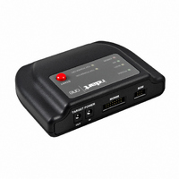
inDART-One
Quickstart Tutorial
CodeWarrior
The inDART-One In-Circuit Programmer/Debugger comes with CodeWarrior
Studio Special Editions for the various Freescale 8- and 16-bit families.
CodeWarrior Development
Studio offers the following
features:
• Editor;
• Assembler;
• Code-size limited C
• Linker;
• Debugger;
• Full-chip simulation;
• Processor Expert.
HC08 Fast Programming Algorithms
Fast programming algorithms significantly reduce the amount of time needed to program
HC08 devices. Fast programming algorithms can be used both in single and multiple program-
ming.
HC08 Target Powering
When working with HC08 devices, the two “TARGET POWER” connectors can be used to
automatically or manually power the target board on and off as required in order to enter
the monitor mode.
Additionally, two configurations are possible: in the first configuration, the “TARGET POWER
IN” connector is routed to the target board via the “TARGET POWER OUT” connector, through
an internal relay driven by inDART-One.
In the second configuration, the voltage at the “TARGET POWER OUT” connector is internally
generated by inDART-One, and the “TARGET POWER IN” connector is not used.
Please refer to the user’s manual for detailed information.
MON08 Connector
inDART-One uses a 16-pin MON08 connector to program and debug HC08 de-
vices. This connector can be configured to work as a standard (P&E compatible)
MON08 connector or as an enhanced (SofTec Microsystems compatible) MON08
connector. The enhanced MON08 connector allows the target microcontroller to
free some lines after entering the monitor mode at reset.
For more information about how to provide the appropriate MON08 connector in
your target board, see “MON08 Target Connections” in the user’s manual.
MC68HC908GP32
MC68HC908QB8
compiler;
MC68HC908AZ60A
Device
Mode A
TM
60Kx8, fCPU = 4MHz
32Kx8, fCPU = 4MHz
8Kx8, fCPU = 4MHz
VDD
OUT
Condition
VDD
IN
Program = 2.7s, Program+Verify = 5.4s
Program = 1.5s, Program+Verify = 2.9s
Program = 1.1s, Program+Trimming+Verify = 1.5s
Mode B
Operation/Time
VDD
OUT
TM
USED
NOT
Development
OSC
VDD
NC
NC
NC
NC
NC
NC
MON08 Connector
(Standard Mode)
15
1
16
2
GND
RST
IRQ
MON4
MON5
MON6
MON7
MON8
Power Connectors
8, 10, 12, 14, 16
1, 3, 5, 7, 9, 11
Microcontroller Development Tools
Pin
13
15
2
4
6
DataBlaze
DataBlaze is a full-feature programming utility suitable for development environment.
DataBlaze offers the following advanced features:
• Memory editing;
• Blank check/erase/program/
• Project handling;
• One-button,
LEDs
verify/read operations/
oscillator trimming
operations;
multiple-operations
programming (“Auto”
feature).
MON4 ... MON8
Signal Name
www.softecmicro.com
GND
RST#
IRQ#
OSC
VDD
NC
System ground.
MCU reset; held at V
microcontroller) out of reset. No other target-system logic
should be tied to this signal.
MCU interrupt; held at V
I/O pins connected to target microcontroller.
This signal can be used as an auxiliary clock source, and is
particularly useful when the target microcontroller requires
an external clock which is not available on the target board.
The target V
When using the MON08 connector in standard mode,
inDART-One can automatically supply this signal.
Not connected.
MON08 Connector
USB Connector
DD
line needs to be driven correctly at reset.
TST
Description
TST
(or V
.
DD
, depending on the target
BDM Connector
Push Button
TGT_MON4
TGT_MON5
TGT_MON6
TGT_MON7
TGT_MON8
RST_OUT
TGT_IRQ
RST_IN
MON08 Connector
(Enhanced Mode)
15
1
2
16
GND
RST
IRQ
MON4
MON5
MON6
MON7
MON8
MultiBlaze
MultiBlaze is an easy-to-use multiple programming utility suitable for production environment.
MultiBlaze offers the following features:
• Up to 32 inDART-One instruments simultaneously controllable from the same PC;
• Easy-to-use programming
• Blank check/erase/program/
• One-button,
• Operator and Supervisor
• Statistics and logging.
IPL Programming Library
The IPL-One programming library is a DLL which includes all of the low-level functions that
allow you to set up the instrument and perform all of the programming commands and func-
tions of the DataBlaze and MultiBlaze programming utilities from within your own Windows
application.
The IPL-One programming library contains C written routines, and can be used to interface the
instrument from within, for example, a Microsoft Visual C or Visual Basic application, as well as
any other programming language that supports the DLL mechanism.
BDM Connector
inDART-One uses the standard, 6-pin BDM connector defined
by Freescale to program and debug HCS08, HCS12 and HCS12X
devices. You must therefore provide such connector (see the
diagram below) on your target board.
interface;
multiple-operations
programming (“Auto”
feature);
mode (password protected);
verify/read operations;
8, 10, 12, 14, 16
7, 9, 11, 13, 15
Pin
Pin
1
2
3
4
5
6
1
2
3
4
5
6
TGT_MON4 ... TGT_MON8
MON4 ... MON8
Signal Name
Signal Name
RST_OUT#
RST#/VPP
TGT_IRQ#
RST_IN#
BKGD
GND
VDD
GND
RST#
IRQ#
NC
NC
Single-wire background interface pin.
System ground.
Not connected.
Reset signal to target system, or V
Not connected.
Power supply voltage from target. This pin is used
by inDART-One for signal conditioning.
Reset signal to target system: GND or open drain
output reflecting the state of the MCU RST# and
RST_IN# signals.
System ground.
Reset signal from target system: GND to V
to control the state of the MCU RST# and
RST_OUT# signals.
MCU reset; held at V
target microcontroller) out of reset. No other
target-system logic should be tied to this signal.
Interrupt signal from target system: GND to V
input to control the state of the MCU IRQ# signal.
MCU interrupt; held at V
signal is not asserted.
I/O pins connected to target application.
I/O pins connected to target microcontroller.
Description
Description
TST
(or V
TST
DD
when the TGT_IRQ#
, depending on the
BKGD
PP
NC
NC
.
BDM Connector
1
5
DD
2
6
input
GND
RST/VPP
VDD
DD


