INDART-ONE/FSL SofTec Microsystems SRL, INDART-ONE/FSL Datasheet
INDART-ONE/FSL
Specifications of INDART-ONE/FSL
INDART-ONE


Related parts for INDART-ONE/FSL


INDART-ONE/FSL Summary of contents
Page 1
User’s Manual ...
Page 2
...
Page 3
... In-Circuit Programmer and Debugger for Freescale 8- and 16-bit Microcontrollers User’s Manual Copyright © 2006 SofTec Microsystems Revision 2.0 ® DC01076 ...
Page 4
... Web: http://www.softecmicro.com Important SofTec Microsystems reserves the right to make improvements to the inDART-One In-Circuit Programmer/Debugger, its documentation and software routines, without notice. Information in this manual is intended to be accurate and reliable. However, SofTec Microsystems assumes no responsibility for its use; nor for any infringements of rights of third parties which may result from its use ...
Page 5
... Contents 0 Before Starting 13 0.1 Important Notice to Users 13 0.2 Required Skills 13 1 Overview 15 1.1 What is inDART-One? 15 1.1.1 In-Circuit Debugger 15 1.1.2 Single Programmer 16 1.1.3 Multiple Programmer 16 1.1.4 inDART Programming Library 16 1.2 Package Contents 16 1.3 Optional HC08 Fast Programming Algorithms 17 1.4 Hardware Overview 17 1.4.1 USB Connector 18 1 ...
Page 6
... Working Principles 35 3.2 Working with CodeWarrior 35 3.2.1 Using the Project Wizard to Create Your Application Skeleton 35 3.2.2 Starting your First Debugging Session 36 3.2.3 Using Existing Projects with inDART-One 37 3.2.4 Breakpoints and Trace 38 3.3 HC08 Notes and Tips 38 3.3.1 Stop Command Handling 38 3.3.2 Breakpoints and Swi Instruction 39 3 ...
Page 7
... MC68H(L)C908JL Family Connections 75 5.3.20 MC68HC908JW Family Connections 75 5.3.21 MC68HC908KX Family Connections 76 5.3.22 MC68HC908LB Family Connections 76 5.3.23 MC68HC908LD Family Connections 77 5.3.24 MC68HC908LJ Family Connections 77 5.3.25 MC68HC908LK Family Connections 78 5.3.26 MC68HC908LT Family Connections 78 5.3.27 MC68HC908LV Family Connections 79 5.3.28 MC68HC908MR Family Connections 79 inDART-One User's Manual ...
Page 8
... Other Settings 88 8 Working with S12(X) Devices 89 8.1 Communication Settings 89 9 inDART Programming Library 93 9.1 Introduction 93 9.2 The inDART Programming Library (IPL) 93 9.3 Installation 93 9.4 Programming Library Reference 94 9.4.1 Using the Interface Library Functions 94 9.4.2 Return Values of the Programming Library Functions 97 9 ...
Page 9
... IPL_WriteDataToBuffer() 127 10 Troubleshooting 129 10.1 Common Problems and Solutions 129 10.1.1 USB Driver Problems 129 10.1.2 Communication Can’t Be Established with inDART-One 129 10.1.3 CodeWarrior-Specific: Stepping Execution is Slow 130 10.1.4 HC08-Specific: Peripheral Speed is Low 130 10.1.5 HCS08-Specific: Communication Lost During Debugging 131 10 ...
Page 10
...
Page 11
... Figure 2.2: New Hardware Wizard, Step 2 30 Figure 2.3: New Hardware Wizard, Step 3 30 Figure 2.4: New Hardware Wizard, Step 4 31 Figure 2.5: inDART-One Control Panel 33 Figure 3.1: The “MCU Configuration” Dialog Box 36 Figure 3.2: The “Set Connection” Dialog Box 37 Figure 3.3: The “ ...
Page 12
... Figure 6.1: The BDM Communication Settings Dialog Box for HCS08 Devices 85 Figure 7.1: The BDM Communication Settings Dialog Box for RS08 Devices 87 Figure 8.1: The BDM Communication Settings Dialog Box for S12(X) Devices 89 Figure 9.1: Typical IPL Workflow 96 Figure 9.2: Programming Buffer 98 Figure 10.1: inDART-One Control Panel 132 ...
Page 13
... Table 1.3: MON08 Connector Signals (Enhanced Mode) 21 Table 1.4: BDM Connector Signals 22 Table 1.5: Status LEDs 23 Table 4.1: MultiBlaze Programming States 53 Table 9.1: IPL Callback Events 120 Table 11.1: Electrical Specifications 133 Table 11.2: Physical and Environmental Specifications 134 inDART-One User's Manual ...
Page 14
...
Page 15
... Required Skills In order to beneficially use the inDART-One In-Circuit Programmer/Debugger, you should be acquainted with certain skills, ranging from hardware design to software design. In particular, you should possess knowledge of the following: Microcontroller systems ...
Page 16
...
Page 17
... Together with CodeWarrior, inDART-One provides you with everything you need to write, compile, download, in-circuit emulate and debug user code. Full-speed program execution allows you to perform hardware and software testing in real time. inDART-One is connected to the host PC through a USB port. inDART-One offers you the following debugging features: Real-time code execution and in-circuit debugging without probes— ...
Page 18
... Single Programmer Additionally, inDART-One is a full-featured programmer, thanks to the provided DataBlaze programming utility. 1.1.3 Multiple Programmer inDART-One instruments can be connected (using USB hubs) to the same PC, allowing for multiple (gang) programming sessions. A specific multiple programming utility, MultiBlaze, is provided. 1.1.4 inDART Programming Library ...
Page 19
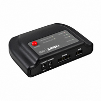
... Table 1.1: Fast Programming Times for Some HC08 Devices See “Unlocking Fast Programming Algorithms” on page 32 for information on how to purchase and setup these features. 1.4 Hardware Overview The following figure shows the various inDART-One connectors. inDART-One User's Manual Programming Times Program = 1.5 s Program + Verify = 2 ...
Page 20
... Overview 1 1.4.1 USB Connector The USB connector is used to connect inDART-One to the host PC. When connecting more then one inDART-One to a host PC, USB hubs can be used. inDART-One is USB 2.0 compliant and uses a high speed connection, but can be connected to USB 1.1 systems as well. inDART-One is powered by the USB bus voltage. ...
Page 21
... For more information about how to provide the appropriate MON08 connector on your target board, see “MON08 Target Connections” on page 63. Figure 1.2: MON08 Connector Signals (Standard Mode) inDART-One User's Manual GND NC ...
Page 22
... The target V line needs to be driven correctly at reset. DD When using the MON08 connector in standard mode, inDART-One can automatically generate this signal. Not connected RST_OUT GND RST_IN ...
Page 23
... CodeWarrior, DataBlaze and MultiBlaze) automatically shows you how to connect that specific device to the MON08 connector. 1.4.3 BDM Connector inDART-One uses the standard, 6-pin BDM connector defined by Freescale to program and debug HCS08, RS08, S12 and S12X devices. You must therefore provide such connector (see the diagram below) on your target board ...
Page 24
... VDD 5 6 BDM Connector Figure 1.4: BDM Connector Signals Description Single-wire background interface pin. System ground. Not connected. Reset signal to target system Not connected. Power supply voltage from target. This pin is used by inDART-One for signal conditioning. Table 1.4: BDM Connector Signals ...
Page 25
... The “START” push-button can be used to start programming the target device, when using the DataBlaze or MultiBlaze programming utilities. Additionally, when using MON08 devices with manual target powering, the “START” button can be used to confirm the target board’s powering on/off, (see “Power Settings” on page 57). inDART-One User's Manual 23 1 ...
Page 26
... Overview 1.5 Software Overview 1 1.5.1 CodeWarrior Development Studio Special Edition The inDART-One In-Circuit Programmer/Debugger comes with CodeWarrior Development Studio Special Editions for the various Freescale HC08, HCS08, RS08, S12 and S12X families. CodeWarrior Development Studio is a powerful and easy-to-use tool suite designed to increase your software development productivity ...
Page 27
... When installing the inDART-One system software you have the option to electronically register the product. If you register the product, you will be automatically notified by e-mail every time a new version of the inDART-One system software is available. inDART-One User's Manual ...
Page 28
... SofTec Microsystems offers its customers a technical support service at support@softecmicro.com. Before getting in contact with us, we advise you to check that you are working with the latest version of the inDART-One system software (upgrades are available free of charge at http://www.softecmicro.com) and to run the diagnostic test (see “Diagnostic Test” ...
Page 29
... Software Setup Note: before connecting the inDART-One board to the PC recommended that you install all of the required software first (see below), so that the inDART-One USB driver will be automatically found by Windows when you connect the board. 2.1.1 Host System Requirements The following hardware and software are required to run the CodeWarrior ...
Page 30
... PC through a USB port. When connecting more than one inDART-One to a host PC, USB hubs can be used. inDART-One is USB 2.0 compliant and uses a high speed connection, but can be connected to USB 1.1 systems as well. inDART-One is powered by the USB bus voltage, and requires a USB port capable of supplying 350 mA. 28 ...
Page 31
... The first time inDART-One is connected to the PC, Windows recognizes the instrument and starts the “Found New Hardware Wizard” procedure, asking you to specify the driver to use for the instrument Windows XP (SP2) the following dialog box will appear, asking you to search for a suitable driver on the web. ...
Page 32
Setup 2 Click the “Next >” button. 3. Depending on your Windows settings, the following warning may appear. 30 Figure 2.2: New Hardware Wizard, Step 2 Figure 2.3: New Hardware Wizard, Step 3 ...
Page 33
... The Starter Kit’s USB driver is now installed on your system. 2.2.2 Target Connection inDART-One connects to your target board either via the MON08 connector or the BDM connector, depending on your hardware’s target device. Additionally, you can take advantage of the Target Power connectors to supply your target board ...
Page 34
... S12(X) Devices”, on page 89 depending on the hardware you are working with. 2.2.3 Communication Settings After physically connecting inDART-One to your target hardware, inDART- One must be configured properly so that communication with the target device can be established correctly. Communication settings are defined through the “Communication Settings” ...
Page 35
... PC at the same time. Once you have the unlocking code(s), do the following: 1. Open the inDART-One Control Panel. Select “Start > Programs > SofTec Microsystems > inDART-One > Control Panel”. The following dialog box will appear. Figure 2.5: inDART-One Control Panel 2. Click the “ ...
Page 36
...
Page 37
... Debugging 3.1 inDART-One Working Principles inDART-One is an in-circuit debugger as well as a programming tool. It programs files into the target microcontroller and offers debugging features like real-time code execution, stepping, and breakpoint. Its debugging features are achieved thanks to the microcontroller’s integrated debug module ...
Page 38
... The first time you enter a debugging session (by selecting “Project > Debug” from the CodeWarrior’s main menu) the “MCU Configuration” dialog box will open, asking you to select the debugging hardware connected to the PC. Make sure that the hardware code is set to “inDART- One”. 36 ...
Page 39
... Using Existing Projects with inDART-One If your project has been targeted to an emulator/simulator other than inDART-One and you wish to use inDART-One as the debugger for your project, please do the following: 1. From the CodeWarrior debugger interface, select “Component > Set Connection”. The “Set Connection” dialog box will appear. ...
Page 40
... Debugging 4. On the CodeWarrior debugger interface a new menu (“inDART-HC08”, “SofTec-HCS08”, “SofTec-RS08” or “inDART-HCS12”) will be created. From this menu, select “Load” and locate the object file your project is based on. 3.2.4 Breakpoints and Trace CodeWarrior offers a variety of tools for analyzing the program flow: breakpoints (both simple and complex), watchpoints and a trace buffer ...
Page 41
... Interrupt Execution during Steps When issuing stepping instructions (Single Step, Step Over, etc.) and there are pending interrupts, inDART-One will not step inside the interrupt handling routine, but the whole interrupt handling routine is executed. An exception is when you single step on an Assembly instruction which branches to itself: in this case, interrupts which may occur are not handled ...
Page 42
Debugging 3.4 HCS08, RS08 and S12(X) Notes and Tips 3.4.1 Entering Debug Session with CodeWarrior When entering a debug session, the target microcontroller’s FLASH memory is automatically erased, unsecured, programmed with the user application, and the trimming value (if trimming ...
Page 43
... RAM locations). For example possible to set the periodical refresh of the “Memory” window contents by choosing “Mode > Periodical” from the pop-up menu which appears by right-clicking on the “Memory” window. inDART-One User's Manual 41 3 ...
Page 44
...
Page 45
... DataBlaze is a full-featured programming utility. DataBlaze offers the following advanced features: Memory editing; Blank check/erase/program/verify/read operations; Project handling; One-button, multiple-operations programming (“Auto” feature); Serial numbering. 4.1.2 Using DataBlaze To start the DataBlaze utility select “Start > Programs > SofTec Microsystems > inDART-One > DataBlaze Programmer”. inDART-One User's Manual 43 4 ...
Page 46
Programming 4 First, select the target device you are working with so, select “Operations > Select Device” from the DataBlaze main menu. The following dialog box will appear. 44 Figure 4.1: The DataBlaze User Interface ...
Page 47
... Figure 4.2: Device Selection If you have more than one inDART-One instrument connected to the USB hub, you can specify which one to use with DataBlaze. Select the device you are working with in the “Device Code” device list and click the “OK” button. ...
Page 48
... Statistics and logging. 4.2.2 Starting MultiBlaze To start the MultiBlaze gang programming utility select “Start > Programs > SofTec Microsystems > inDART-One > MultiBlaze Programmer”. The following dialog box will appear. MultiBlaze requires you to log in, either as supervisor or operator, with your username and password. Logging in as supervisor allows you to set Figure 4 ...
Page 49
... Before to start a programming session, you must first create a project. To create a project, click the “New Project” button. You will be guided through a wizard that will help you select your target device, the file to be programmed, and the inDART-One instruments to be used. Note: creating or editing a project is only possible if you i have logged in as supervisor ...
Page 50
Programming On the first wizard step, you must specify a name for the project and the path where the project file will be saved. You must also specify the target device you are going to program, and you must specify ...
Page 51
... Additionally, you can specify how to start programming. Programming can be started by either clicking the “Start” button on the Program dialog box (see below pressing the “Start” button on each inDART-One instrument. Note: clicking the “Start” button in the Program dialog box i causes all instruments to start programming simultaneously. Pressing the “ ...
Page 52
... The “Autofill” button can be used to automatically detect each inDART-One instrument connected to the USB bus and assign programming node. Only inDART-One instruments specified in this wizard step will be used during programming sessions ...
Page 53
... Once a project is loaded (via the “Open Project” button) or after a project has been created (via the “New Project” button) programming sessions can be performed. To start a programming session, click the “Program” button. The following dialog box will appear. inDART-One User's Manual 51 4 ...
Page 54
... Programming 4 For each of the inDART-One instruments specified in your project, an icon is present which indicates the status of that instrument. Possible states are listed in the table below. 52 Figure 4.9: MultiBlaze Programming Window ...
Page 55
... Depending on the project settings, you can start programming by either clicking the “Start” button in the “Program” dialog box (all instruments start programming simultaneously) or press the “Start” button on any inDART- One instrument (only that instrument will perform programming). A log file with the details of the programming session is automatically saved in the project directory ...
Page 56
Programming 4.3 BDM Programming Notes The “Mass Erase” operation always blanks the device (even if the device is protected or secured) and “unsecures” the device (the FLASH Options/Security Byte location is programmed with 0xFE). The “Blank Check” operation doesn’t blank ...
Page 57
... Working with HC08 Devices 5.1 Debugging Limitations Since inDART-One is based on the in-chip debugging features of the HC08 family of microcontrollers, some hardware and software limitations apply. The main ones are listed below; for the complete list of limitations please refer to the microcontroller’s data sheet. ...
Page 58
... MON4 or MON5 line is dedicated to the single- wire communication (which is reserved during debugging). The other MON lines must be driven at specific values at reset. inDART-One automatically drives all of the required lines upon reset, and releases them soon afterwards (except for the single-wire communication line which is always reserved) ...
Page 59
... Note, however, that not all peripherals will work at this doubled speed. 5.2.2 Power Settings The parameters in this group are used by inDART-One to determine how to force the target microcontroller to enter the monitor mode. inDART-One User's Manual ...
Page 60
... Depending on your target hardware, two possibilities are available: Automatic. Select this option if you want inDART-One to automatically turn off and on the target system in order to enter the monitor mode. In order for this option to work, the target system must be powered through the “ ...
Page 61
... POWER OUT” connector, through an internal relay driven by inDART-One. When the second option (“Mode B”) is selected, the voltage at the “TARGET POWER OUT” connector is internally generated by inDART-One, and the “TARGET POWER IN” connector is not used. The generated voltage is as specified by the “Target Voltage Selection” parameter. ...
Page 62
... Working with HC08 Devices Note: when the MON08 connector is configured as i “Standard (Multilink Compatible)” connector, the target voltage is also generated by inDART-One at the pin 15 of the MON08 connector. 5.2.3 Programming Programming parameters mainly determine the speed at which programming operations are performed. ...
Page 63
... The “Target Baud Rate” parameter specifies the MON08 serial line’s baud rate used to enter the monitor mode. inDART-One can automatically determine the correct target baud rate in the most common situations; the “Automatic Detection” is the default option. However, if for some reasons the automatic detection doesn’ ...
Page 64
... The standard verify mode is the safest mode, while the checksum verify mode is the fastest. Note: the “Verify Mode” parameter is only available when i using the DataBlaze or MultiBlaze user interface. 5.2.4 Trimming inDART-One allows you to enable the target microcontroller’s internal oscillator calibration (trimming). 5 Figure 5.6: MON08 Communication Settings: Trimming 62 ...
Page 65
... Trimming Location” parameter). 5.3 MON08 Target Connections 5.3.1 Standard MON08 Connections The following diagram illustrates a typical connection between your target microcontroller and the MON08 connector, when inDART-One is configured to use the standard (Multilink compatible) MON08 connector. inDART-One User's Manual 63 5 ...
Page 66
... Figure 5.7: Typical MON08 Target Connections (Standard Mode) Note: the target V i reset. When using the MON08 connector in standard mode, inDART-One can automatically supply the connector’s pin 15 with the appropriate voltage. Note: the MON08 OSC signal (pin 13 of the MON08 i ...
Page 67
... MON4-MON8 lines must be therefore tied to the appropriate pins of the specific target microcontroller. 5.3.2 Enhanced MON08 Connections The following diagram illustrates a typical connection between your target microcontroller and the MON08 connector, when inDART-One is configured to use the enhanced (SofTec Microsystems) MON08 connector. RST_OUT RST_IN TGT_IRQ ...
Page 68
... MON4-MON8 lines must be therefore tied to the appropriate pins of the specific target microcontroller. If your target board implements the enhanced MON08 connector, to work without inDART-One connected then the MON08 connector must be jumpered as shown below on the left. 5 Enhanced MON08 connector jumpered ...
Page 69
... Figure 5.10: Standard MON08 Connections for the MC68HC908AB Family 5.3.4 MC68HC908AP Family Connections Standard MON08 connections for MC68HC908AP family devices are shown in the figure below. Figure 5.11: Standard MON08 Connections for the MC68HC908AP Family inDART-One User's Manual GND NC ...
Page 70
Working with HC08 Devices 5.3.5 MC68HC908AS Family Connections Standard MON08 connections for MC68HC908AS family devices are shown in the figure below. 5 Figure 5.12: Standard MON08 Connections for the MC68HC908AS Family 5.3.6 MC68HC908AZ Family Connections Standard MON08 connections for MC68HC908AZ ...
Page 71
... Figure 5.14: Standard MON08 Connections for the MC68HC908BD Family 5.3.8 MC68HC908EY Family Connections Standard MON08 connections for MC68HC908EY family devices are shown in the figure below. Figure 5.15: Standard MON08 Connections for the MC68HC908EY Family inDART-One User's Manual GND NC ...
Page 72
Working with HC08 Devices 5.3.9 MC68HC908GP Family Connections Standard MON08 connections for MC68HC908GP family devices are shown in the figure below. 5 Figure 5.16: Standard MON08 Connections for the MC68HC908GP Family 5.3.10 MC68HC908GR4/4A/8/8A Connections Standard MON08 connections for MC68HC908GR4/4A/8/8A devices ...
Page 73
... Standard MON08 connections for the MC68HC908GR16 device are shown in the figure below. Figure 5.18: Standard MON08 Connections for the MC68HC908GR16 Device 5.3.12 MC68HC908GR16A/32A/48A/60A Connections Standard MON08 connections for MC68HC908GR16A/32A/48A/60A devices are shown in the figure below. Figure 5.19: Standard MON08 Connections for MC68HC908GR16A/32A/48A/60A Devices inDART-One User's Manual GND NC RST ...
Page 74
Working with HC08 Devices 5.3.13 MC68HC908GT Family Connections Standard MON08 connections for MC68HC908GT family devices are shown in the figure below. 5 Figure 5.20: Standard MON08 Connections for the MC68HC908GT Family 5.3.14 MC68HC908GZ Family Connections Standard MON08 connections for MC68HC908GZ ...
Page 75
... Standard MON08 connections for the MC68HC908JB8 device are shown in the figure below. Figure 5.22: Standard MON08 Connections for the MC68HC908JB8 Device 5.3.16 MC68HC908JB12/16 Connections Standard MON08 connections for MC68HC908JB12/16 devices are shown in the figure below. Figure 5.23: Standard MON08 Connections for MC68HC908JB12/16 Devices inDART-One User's Manual GND NC RST ...
Page 76
Working with HC08 Devices 5.3.17 MC68HC908JG Connections Standard MON08 connections for MC68HC908JG family devices are shown in the figure below. 5 Figure 5.24: Standard MON08 Connections for the MC68HC908JG Family 5.3.18 MC68H(L)C908JK Family Connections Standard MON08 connections for MC68H(L)C908JK family ...
Page 77
... Figure 5.26: Standard MON08 Connections for the MC68H(L)C908JL Family 5.3.20 MC68HC908JW Family Connections Standard MON08 connections for MC68HC908JW family devices are shown in the figure below. Figure 5.27: Standard MON08 Connections for the MC68HC908JW Family inDART-One User's Manual GND NC ...
Page 78
Working with HC08 Devices 5.3.21 MC68HC908KX Family Connections Standard MON08 connections for MC68HC908KX family devices are shown in the figure below. 5 Figure 5.28: Standard MON08 Connections for the MC68HC908KX Family 5.3.22 MC68HC908LB Family Connections Standard MON08 connections for MC68HC908LB ...
Page 79
... Figure 5.30: Standard MON08 Connections for the MC68HC908LD Family 5.3.24 MC68HC908LJ Family Connections Standard MON08 connections for MC68HC908LJ family devices are shown in the figure below. Figure 5.31: Standard MON08 Connections for the MC68HC908LJ Family inDART-One User's Manual GND NC ...
Page 80
Working with HC08 Devices 5.3.25 MC68HC908LK Family Connections Standard MON08 connections for MC68HC908LK family devices are shown in the figure below. 5 Figure 5.32: Standard MON08 Connections for the MC68HC908LK Family 5.3.26 MC68HC908LT Family Connections Standard MON08 connections for MC68HC908LT ...
Page 81
... Figure 5.34: Standard MON08 Connections for the MC68HC908LV Family 5.3.28 MC68HC908MR Family Connections Standard MON08 connections for MC68HC908MR family devices are shown in the figure below. Figure 5.35: Standard MON08 Connections for the MC68HC908MR Family inDART-One User's Manual GND NC ...
Page 82
Working with HC08 Devices 5.3.29 MC68HC908QB Family Connections Standard MON08 connections for MC68HC908QB family devices are shown in the figure below. 5 Figure 5.36: Standard MON08 Connections for the MC68HC908QB Family 5.3.30 MC68HC908QC Family Connections Standard MON08 connections for MC68HC908QC ...
Page 83
... Figure 5.38: Standard MON08 Connections for the MC68HC908QF Family 5.3.32 MC68HC908QL Family Connections Standard MON08 connections for MC68HC908QL family devices are shown in the figure below. Figure 5.39: Standard MON08 Connections for the MC68HC908QL Family inDART-One User's Manual GND NC ...
Page 84
Working with HC08 Devices 5.3.33 MC68H(L)C908QT Family Connections Standard MON08 connections for MC68H(L)C908QT family devices are shown in the figure below. 5 Figure 5.40: Standard MON08 Connections for the MC68HC908QT Family 5.3.34 MC68H(L)C908QY Family Connections Standard MON08 connections for MC68H(L)C908QY ...
Page 85
... Figure 5.42: Standard MON08 Connections for the MC68HC908RF Family 5.3.36 MC68HC908RK Family Connections Standard MON08 connections for MC68HC908RK family devices are shown in the figure below. Figure 5.43: Standard MON08 Connections for the MC68HC908RK Family inDART-One User's Manual GND NC ...
Page 86
Working with HC08 Devices 5.3.37 MC68HC908SR Family Connections Standard MON08 connections for MC68HC908SR family devices are shown in the figure below. 5 Figure 5.44: Standard MON08 Connections for the MC68HC908SR Family GND NC RST NC IRQ ...
Page 87
... Working with HCS08 Devices 6.1 Communication Settings inDART-One must be configured properly so that BDM communication with the target device can be established correctly. Communication settings are defined through the “Communication Settings” dialog box, available both in CodeWarrior and in the DataBlaze and MultiBlaze programming utilities. ...
Page 88
... The “RESET Rise Time” parameter specifies the time, in milliseconds, needed for the target RESET signal to go high. This value depends on the target system, and is used by inDART-One to generate the appropriate delay before to drive the BKGD line correctly in order to enter the special single chip mode ...
Page 89
... Working with RS08 Devices 7.1 Communication Settings inDART-One must be configured properly so that BDM communication with the target device can be established correctly. Communication settings are defined through the “Communication Settings” dialog box, available both in CodeWarrior and in the DataBlaze and MultiBlaze programming utilities. ...
Page 90
... Other Settings The “TARGET POWER OUT Voltage” parameter specifies the voltage provided by inDART-One on the “TARGET POWER OUT” connector, which can be used to power up the target board. Note: only the central pin of the “TARGET POWER OUT” ...
Page 91
... Working with S12(X) Devices 8.1 Communication Settings inDART-One must be configured properly so that BDM communication with the target device can be established correctly. Communication settings are defined through the “Communication Settings” dialog box, available both in CodeWarrior and in the DataBlaze and MultiBlaze programming utilities. ...
Page 92
... In order for this feature to work, an appropriate loop filter circuitry must be provided to the device’s XFC pin. The “TARGET POWER OUT Voltage” parameter specifies the voltage provided by inDART-One on the “TARGET POWER OUT” connector, which can be used to power up your target board. 90 ...
Page 93
... The “RESET Rise Time” parameter specifies the time, in milliseconds, needed for the target RESET signal to go high. This value depends on the target system, and is used by inDART-One to generate the appropriate delay before to drive the BKGD line correctly in order to enter the special single chip mode ...
Page 94
...
Page 95
... Installation Before to start working with the inDART Programming Library, you must set up your system with all the required files and drivers. The files to be installed are: The “sftdrv01.sys” file in “Windows\System32\Drivers”; ...
Page 96
... These files are automatically installed by the inDART-One Utilities setup, as described in “inDART-One Utilities Setup” on page 28. 9.4 Programming Library Reference 9.4.1 Using the Interface Library Functions When you control one or more inDART-One within your own application, you will typically follow the steps indicated below: 1. Initialize the programming session. ...
Page 97
... The figure below illustrates a typical working flow. inDART-One User's Manual 95 9 ...
Page 98
... Programming Library Optional Instrument Network Configuration Target Device Selection and Configuration Programming Steps Definition Programming Buffer Definition IPL_WriteDataToBuffer() Programming 9 96 IPL_StartSession() IPL_GetInstrumentsConnected() IPL_SetInstrumentsConfiguration() IPL_SetCallBack() IPL_GetDeviceList() IPL_SetDevice() IPL_SetCommunicationSettings() IPL_GetDefaultProgrammingSteps() IPL_SetProgrammingSteps() IPL_LoadFileIntoBuffer() IPL_StartProgramming() IPL_GetInstrumentStatus() IPL_EndSession() Figure 9.1: Typical IPL Workflow ...
Page 99
... Return Values of the Programming Library Functions Most of the inDART Programming Library functions return a BOOL value which indicates whether the function was successfully executed (return value = TRUE) or not (return value = FALSE). In the latter case it is possible to get extended error information by calling the function IPL_GetError: void IPL_GetError(char *error_string) ...
Page 100
... Programming Library User Application IPL_ReadDeviceMemoryIntoBuffer() IPL_ReadDeviceMemoryIntoBuffer() IPL_StartProgramming() Note: the programming buffer size is automatically set to the i target device’s memory size, after the IPL_SetDevice() function is called. 9.5 Function Reference Each Programming Library function is listed alphabetically and explained in the following pages. 9.5.1 Typedefs and Structures Listed below are the various typedefs and structures used by the IPL-One functions ...
Page 101
... IPL_STEP_CODE_BLANK IPL_STEP_CODE_ERASE IPL_STEP_CODE_PROGRAM IPL_STEP_CODE_VERIFY IPL_STEP_DATA_BLANK IPL_STEP_DATA_ERASE IPL_STEP_DATA_PROGRAM IPL_STEP_DATA_VERIFY IPL_STEP_TRIM_PROG IPL_STEP_RUN IPL_STEP_CODE_READ IPL_STEP_DATA_READ IPL_STEP_NOT_SUPPORTED IPL_STEP_TARGET_OFF } IPL_PROG_STEP; typedef enum { IPL_STATUS_IDLE IPL_STATUS_WORKING IPL_STATUS_ERR_COMMUNICATION IPL_STATUS_ERR_INTERNAL IPL_STATUS_ERR_BLANKCHECK_DEVICE IPL_STATUS_ERR_READ_DEVICE IPL_STATUS_ERR_ERASE_DEVICE IPL_STATUS_ERR_PROGRAM_DEVICE IPL_STATUS_ERR_VERIFY_DEVICE IPL_STATUS_ERR_PROTECTION_DEVICE IPL_STATUS_ERR_INVALID_DEVICE } IPL_INST_STATUS_MODE; inDART-One User's Manual = 10, = 11, = 12 ...
Page 102
... Programming Library typedef enum { IPL_EVENT_PROG_START IPL_EVENT_PROG_END IPL_EVENT_PROG_STEP IPL_EVENT_ERROR } IPL_EVENT_TYPE; typedef struct _IPL_DEVICE_LIST { char device_code[50]; char family_code[20]; } IPL_DEVICE_LIST; typedef struct _IPL_INST_INFO { unsigned int SN; BOOL driver_busy; } IPL_INST_INFO; typedef struct _IPL_INST_CONFIG { unsigned int SN; int ID; } IPL_INST_CONFIG; typedef struct _IPL_INST_STATUS { IPL_INST_STATUS_MODE mode; char message[MAXLEN_ERROR_MSG]; } IPL_INST_STATUS; ...
Page 103
... IPL_EVENT_TYPE event_type, void *event_data); inDART-One User's Manual 101 9 ...
Page 104
... Programming Library 9.5.2 IPL_EndSession() Include file: #include “IPL-One.h” Function prototype: BOOL IPL_EndSession(void); Parameters: None. Return value: TRUE: FALSE: Description: Ends a programming “session”. All of the Programming Library functions (exception made for the IPL_GetVersion() function) must be called within a IPL_StartSession() and IPL_EndSession() function ...
Page 105
... Return value: the function was successful. TRUE: an error occurred. Call the IPL_GetError() FALSE: function to get extended error information. Description: Calculates and returns the checksum of the programming buffer. inDART-One User's Manual 103 9 ...
Page 106
... Return value: TRUE: FALSE: Description: 9 This function reads the status of the “START” button of the specified inDART-One instruments. If the “START” button is pressed, the pressed parameter will be TRUE. 104 ID of the inDART-One instrument (previously set via the IPL_SetInstrumentConfiguration() function). TRUE if the “START” button is pressed, FALSE otherwise ...
Page 107
... Note: calling this function when the specified inDART- i One instrument is busy programming will always result in the pressed parameter to be FALSE. inDART-One User's Manual 105 9 ...
Page 108
... Programming Library 9.5.5 IPL_GetDefaultProgrammingSteps() Include file: #include “IPL-One.h” Function prototype: BOOL IPL_GetDefaultProgrammingSteps( IPL_PROG_STEP *prog_steps, int n_items, int *items_found); Parameters: prog_steps: n_items: items_found: Return value: TRUE: FALSE: Description: Fills an array (prog_steps) with the default programming steps for the currently selected target device. The function returns n_items. ...
Page 109
... Tip: you can first call: IPL_GetDefaultProgrammingSteps(NULL, 0, *no_of_prog_steps); to get the number of programming steps, and then call: IPL_GetDefaultProgrammingSteps(*tot_steps, no_of_prog_steps, NULL); to retrieve them all. inDART-One User's Manual 107 9 ...
Page 110
... Programming Library 9.5.6 IPL_GetDeviceList() Include file: #include “IPL-One.h” Function prototype: BOOL IPL_GetDeviceList( IPL_DEVICE_LIST *device_list, int n_items, int *items_found); Parameters: device_list: n_items: items_found: Return value: TRUE: FALSE: Description: Fills an array (device_list) with devices supported by the IPL-One Programming Library. The function extracts n_items from the 9 Programming Library device list ...
Page 111
... Tip: you can first call: IPL_GetDeviceList(NULL, 0, *no_of_devices); to get the number of devices, and then call: IPL_GetDeviceList(*tot_list, no_of_devices, NULL); to retrieve them all. inDART-One User's Manual 109 9 ...
Page 112
... Programming Library 9.5.7 IPL_GetError() Include file: #include “IPL-One.h” Function prototype: void IPL_GetError(char *error_string); Parameters: error_string: this parameter will be filled with a text message Return value: None. Description: Most of the Programming Library functions return a BOOL value which indicates whether the function was successfully executed (return value = TRUE) or not (return value = FALSE) ...
Page 113
... Call the IPL_GetError() FALSE: function to get extended error information. Description: Fills an array (inst_info) with information about inDART-One instruments connected to the USB bus. The function returns n_items. The items_found variable will contain the actual number of inDART-One instruments found. Tip: you can first call: IPL_GetInstrumentsConnected(NULL, 0, *no_of_inst) ...
Page 114
... Programming Library to get the number of all of the inDART-One instruments connected to the USB bus, and then call: IPL_GetInstrumentsConnected(*tot_inst, no_of_inst, NULL); to retrieve information about all of them. 9 112 ...
Page 115
... IPL_GetInstrumentStatus() Include file: #include “IPL-One.h” Function prototype: BOOL IPL_GetInstrumentStatus( int inst_ID, IPL_INST_STATUS *status); Parameters the inDART-One instrument (previously set inst_ID: via the IPL_SetInstrumentConfiguration() function). pointer to an IPL_INST_STATUS structure that will status: receive status information. Return value: the function was successful. ...
Page 116
... Programming Library 9.5.10 IPL_GetVersion() Include file: #include “IPL-One.h” Function prototype: void IPL_GetVersion(char *ver); Parameters: this parameter will be filled with a string containing the ver: version of the IPL-One DLL and related DLLs. Return value: None. Description: Call this function to get version information about the IPL-One Programming Library and related DLLs ...
Page 117
... That is, the programming buffer is filled starting from the buffer_offset address. Valid only when file_format is IPL_FORMAT_BINARY. Return value: the function was successful. TRUE: inDART-One User's Manual IPL_FORMAT_BINARY (for binary files); IPL_FORMAT_IHEX (for Intel-Hex files); IPL_FORMAT_S19 (for Motorola S-Record files). 9 115 ...
Page 118
... Programming Library FALSE: Description: Loads the contents of an external file into the programming buffer. 9 116 an error occurred. Call the IPL_GetError() function to get extended error information. ...
Page 119
... Call the IPL_GetError() FALSE: function to get extended error information. Description: Reads data from the programming buffer. Since the programming buffer is a one-to-one mapping of the target device memory, the addr parameter corresponds to a target device memory address. inDART-One User's Manual 117 9 ...
Page 120
... IPL_ReadDataFromBuffer() function. To check the status of the reading operation, call the IPL_GetInstrumentStatus() function. 9 118 ID of the inDART-One instrument (previously set via the IPL_SetInstrumentConfiguration() function) to read from. the function was successful. an error occurred. Call the IPL_GetError() function to get extended error information. ...
Page 121
... Library each time a meaningful event occurs. The callback function prototype is: void (*IPL_CALLBACK)( int inst_ID, IPL_EVENT_TYPE event_type, void *event_data); where inst_ID is the instrument that generated the event, event_type is the type of event and event_data is additional information regarding the event (if available). Possible events are summarized in the table below. inDART-One User's Manual 119 9 ...
Page 122
... Programming Library Event ( event_type IPL_EVENT_PROG_START IPL_EVENT_PROG_END IPL_EVENT_PROG_STEP IPL_EVENT_ERROR i 9 120 ) Description Occurs after the IPL_StartProgramming() function is called. No event information is passed to the callback function ( Occurs at the end of programming, i.e. after all of the programming steps are performed. No event information is passed to the callback function ...
Page 123
... TRUE: an error occurred. Call the IPL_GetError() FALSE: function to get extended error information. Description: Initializes inDART-One with target device information. This initialization procedure must be done before calling any other function that reads from/writes to the target device. inDART-One User's Manual 121 9 ...
Page 124
... Programming Library 9.5.16 IPL_SetDevice() Include file: #include “IPL-One.h” Function prototype: BOOL IPL_SetDevice(const char *device_code); Parameters: device_code: Return value: TRUE: FALSE: Description: Sets the target device to be programmed. To retrieve a list of supported devices, call the IPL_GetDeviceList() function. 9 122 the string containing the complete device code. ...
Page 125
... Call the IPL_GetError() FALSE: function to get extended error information. Description: Configures one or more inDART-One instruments. The config parameter is a pointer to an array of IPL_INST_CONFIG structures which associate each instrument’s serial number to a logical ID. Note: this function can be called only once between ...
Page 126
... Programming Library 9.5.18 IPL_SetProgrammingSteps() Include file: #include “IPL-One.h” Function prototype: BOOL IPL_SetProgrammingSteps( IPL_PROG_STEP *prog_steps, int n_items); Parameters: prog_steps: n_items: Return value: TRUE: FALSE: Description: Sets the programming steps to be performed when calling the IPL_StartProgramming() function. To retrieve the default programming steps available for the currently selected target device, call the IPL_GetDefaultProgrammingSteps() function ...
Page 127
... IPL_StartProgramming() Include file: #include “IPL-One.h” Function prototype: BOOL IPL_StartProgramming(int inst_ID); Parameters the inDART-One instrument (previously set inst_ID: via the IPL_SetInstrumentConfiguration() function). Return value: the function was successful. TRUE: an error occurred. Call the IPL_GetError() FALSE: function to get extended error information. ...
Page 128
... Starts a programming “session”. All of the Programming Library functions (exception made for the IPL_GetVersion() function) must be called within an IPL_StartSession() and IPL_EndSession() function. The IPL_StartSession() function detects all inDART-One instruments connected to the USB bus and determines whether fast programming algorithms are unlocked. 9 126 the function was successful ...
Page 129
... Writes data to the programming buffer. The contents of the programming buffer will be programmed into the target device with the IPL_StartProgramming() function. Since the programming buffer is a one-to-one mapping of the target device memory, the addr parameter corresponds to a target device memory address. inDART-One User's Manual 127 9 ...
Page 130
...
Page 131
... Double click on this device the “General” tab, click the “Reinstall Driver” button. Follow the on- screen instructions. 10.1.2 Communication Can’t Be Established with inDART-One 1. Make sure that inDART-One is connected to the PC and powered on. inDART-One is powered by the USB connection. inDART-One User's Manual 129 10 ...
Page 132
... The MON08/BDM cable is connected to the target board. All of the required MON08/BDM connector signals are correctly tied to the target microcontroller. 3. Make sure you are working with the correct inDART hardware model view/change the inDART hardware model in use in CodeWarrior, choose “Connect” (or “Communication”) from the “ ...
Page 133
... The SOPT register can be written only once after reset. 10.2 Diagnostic Test inDART-One has built-in self-test capabilities. This means that you can verify by yourself, at any time, the correct operation of the instrument’s hardware. To perform the diagnostic test: 1. Open the inDART-One Control Panel. Select “ ...
Page 134
... SofTec Microsystems offers its customers a free technical support service at support@softecmicro.com. Before getting in contact with us, we advise you to check that you are working with the latest version of the inDART-One system software (upgrades are available free of charge at http://www.softecmicro.com). Additional resources can be found on our online discussion forums (http://www ...
Page 135
... MON08 mode, pin 15) MON08 connector OSC signal (standard MON08 mode, pin 13) BDM Section BDM connector VDD signal (pin 6) BDM connector BKGD signal (pin 1) Table 11.1: Electrical Specifications inDART-One User's Manual Value (provided by the USB bus) 350 mA (max DC 5.0 V DC, 200 mA 3.3 V DC, 100 mA 2 ...
Page 136
... Coaxial power jack, center pin (positive) = 2.1 mm, outer sleeve = 5.5 mm 0°C to 50°C 0°C to 70°C 90% (without condensation) Table 11.2: Physical and Environmental Specifications inDART-One User's Manual ...
Page 137
...
Page 138
...
Page 139
...
Page 140
Copyright © SofTec Microsystems®. Freescale™ and the Freescale logo are trademarks of Freescale Semiconductor, Inc igned by ...