EVAL6599-200W STMicroelectronics, EVAL6599-200W Datasheet - Page 16
EVAL6599-200W
Manufacturer Part Number
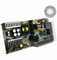
EVAL6599-200W
Description
EVAL BOARD FOR L6599
Manufacturer
STMicroelectronics
Type
Power Factor Correctionr
Specifications of EVAL6599-200W
Main Purpose
AC/DC, Primary Side and PFC
Outputs And Type
4, Isolated
Power - Output
200W
Voltage - Output
24V, 12V, 5V, 3.3V
Current - Output
6A, 5A, 1A, 700mA
Voltage - Input
90 ~ 264VAC
Regulator Topology
Resonant
Frequency - Switching
95kHz
Board Type
Fully Populated
Utilized Ic / Part
L6563, L6599
Input Voltage
90 V to 264 V
Output Voltage
3.3 V to 24 V
Dimensions
132 mm x 265 mm
Product
Power Management Modules
Lead Free Status / RoHS Status
Lead free / RoHS Compliant
For Use With/related Products
L6599
Other names
497-5496


Electrical test results
2.5
16/35
Figure 14. +24 V output short-circuit
Short circuit on +24 V output voltage
Ch1: +24 V output voltage
Ch2: L6599 pin 6 (ISEN)
Ch3: L6599 pin 2 (DELAY)
Ch4: +24 V output current
side of the figure the very low mean current flowing in the shorted output which is less than
0.3 A.
Overvoltage protection
Both the PFC pre-regulator and the resonant converter are equipped with their own over-
voltage protection circuit. The PFC controller L6563 is internally equipped with a dynamic
and a static overvoltage protection circuit sensing the error amplifier via the voltage divider
dedicated to the feedback loop to sense the PFC output voltage. If an internal threshold is
exceeded, the IC limits the PFC output voltage to a programmable, safe value.
Moreover, in the L6563 there is an additional protection against loop failures using an
additional divider (R5, R7, R9, R16 and R25) connected to a dedicated pin (PFC_OK, Pin 7)
protecting the circuit in case of loop failures or disconnection or deviation from the nominal
value of the feedback loop divider. Hence the PFC output voltage is always under control
and in case a fault condition is detected the PFC_OK circuitry will latch the L6563
operations and, by means of the PWM_LATCH pin (Pin 8) it will latch the L6599 as well via
the DIS pin (Pin 8).
The OVP circuit (see
zener diodes (D21 and D23) to sense the +24 V and+12 V. If one of the output voltages
exceeds the threshold imposed by these zener diodes plus the V
Q9 starts conducting and the optocoupler U8 opens Q7, so that the V
the controller ICs L6563 and L6599 is no longer available. This state is latched until a mains
voltage recycle occurs.
waveforms
Figure
4) for the output voltages of the resonant converter uses two
Figure 15. +12 V output short-circuit
Short circuit on +12 V output voltage
Ch1: +12 V output voltage
Ch2: L6599 pin 6 (ISEN)
Ch3: L6599 pin 2 (DELAY)
Ch4: +12 V output current
waveforms
BE
of Q10, the transistor
AUX
supply voltage of
AN2393
Related parts for EVAL6599-200W
Image
Part Number
Description
Manufacturer
Datasheet
Request
R

Part Number:
Description:
EVAL BOARD FOR L6599
Manufacturer:
STMicroelectronics
Datasheet:

Part Number:
Description:
DEMO BOARD FOR L6599
Manufacturer:
STMicroelectronics
Datasheet:

Part Number:
Description:
DEMO BOARD FOR L6599
Manufacturer:
STMicroelectronics
Datasheet:

Part Number:
Description:
STMicroelectronics [RIPPLE-CARRY BINARY COUNTER/DIVIDERS]
Manufacturer:
STMicroelectronics
Datasheet:
Part Number:
Description:
STMicroelectronics [LIQUID-CRYSTAL DISPLAY DRIVERS]
Manufacturer:
STMicroelectronics
Datasheet:

Part Number:
Description:
BOARD EVAL FOR MEMS SENSORS
Manufacturer:
STMicroelectronics
Datasheet:
Part Number:
Description:
NPN TRANSISTOR POWER MODULE
Manufacturer:
STMicroelectronics
Datasheet:
Part Number:
Description:
TURBOSWITCH ULTRA-FAST HIGH VOLTAGE DIODE
Manufacturer:
STMicroelectronics
Datasheet:
Part Number:
Description:
Manufacturer:
STMicroelectronics
Datasheet:
Part Number:
Description:
DIODE / SCR MODULE
Manufacturer:
STMicroelectronics
Datasheet:
Part Number:
Description:
DIODE / SCR MODULE
Manufacturer:
STMicroelectronics
Datasheet:
Part Number:
Description:
Search -----> STE16N100
Manufacturer:
STMicroelectronics
Datasheet: