MPC566EVB Freescale Semiconductor, MPC566EVB Datasheet - Page 46
MPC566EVB
Manufacturer Part Number
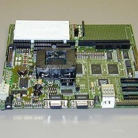
MPC566EVB
Description
KIT EVALUATION FOR MPC565/566
Manufacturer
Freescale Semiconductor
Specifications of MPC566EVB
Processor To Be Evaluated
MPC56x
Data Bus Width
32 bit
Interface Type
RS-232, Ethernet
Lead Free Status / RoHS Status
Contains lead / RoHS non-compliant


MPC566EVB Jumper and Switch Setup
2.2.7 Using a Personal Computer as a Terminal
A personal computer may be used as a terminal provided a terminal emulation software package is
available. Examples of this software are AxIDE, TeraTerm, PROCOMM, KERMIT, QMODEM,
Windows 95/98/2000 HyperTerminal or similar packages. The board should then be connected as
described in Section 2.2.6, “Connecting the Terminal.”
Once the connection to the PC is made, power may be applied to the PC and the terminal emulation
software can be run. In terminal mode, it is neccessary to select the baud rate and character format
for the channel. The character format should be 8 bits, no parity, one stop bit. (see Section 2.2.5,
“The Terminal Character Format”.) The baud rate should be set to 19200 and XON/XOFF flow
control should be turn on. Power can now be applied to the board.
Pin assignments are as follows.
Pin 1, 4, and 6 = group connected for DTR/DSR flow control null back to host
Pin 2 = TXD output (RS232 level)
Pin 3 = RXD input (RS232 level)
Pin 5 = Ground/Vss/Common
Pin 7 and 8 = group connected for RTS/CTS flow control null back to host
Pin 9 = open
2.3 MPC566EVB Jumper and Switch Setup
Jumper settings are as follows:
Note ‘*’ is used to indicate that default setting.
‘**’ is used to indicate mandatory setting for proper operation.
2-6
JP1
JP2
JP3
Figure 2-2. Pin assignment for female (Terminal) connector.
Jumper Setting
* 1-2,3-4
1-3,2-4
*1-2 (closest to
BDM_PORT)
Freescale Semiconductor, Inc.
For More Information On This Product,
5
Table 2-2. Jumper Settings
MPC566EVB User’s Manual
9
Go to: www.freescale.com
COM2: TX=Pin3, RX=Pin2 (see silk screen on bottom of
board)
COM2: TX=Pin2, RX=Pin3 (see silk screen on bottom of
board)
Determines the display power pin polarity on the
LCD_PORT. See the schematic
BDM being used runs at 3.3 volts. So the signals need to go
through a level shifter to get 2.6 volts to the part.
6
Function
1
Related parts for MPC566EVB
Image
Part Number
Description
Manufacturer
Datasheet
Request
R

Part Number:
Description:
Manufacturer:
Freescale Semiconductor, Inc
Datasheet:
Part Number:
Description:
Manufacturer:
Freescale Semiconductor, Inc
Datasheet:
Part Number:
Description:
Manufacturer:
Freescale Semiconductor, Inc
Datasheet:
Part Number:
Description:
Manufacturer:
Freescale Semiconductor, Inc
Datasheet:
Part Number:
Description:
Manufacturer:
Freescale Semiconductor, Inc
Datasheet:
Part Number:
Description:
Manufacturer:
Freescale Semiconductor, Inc
Datasheet:
Part Number:
Description:
Manufacturer:
Freescale Semiconductor, Inc
Datasheet:
Part Number:
Description:
Manufacturer:
Freescale Semiconductor, Inc
Datasheet:
Part Number:
Description:
Manufacturer:
Freescale Semiconductor, Inc
Datasheet:
Part Number:
Description:
Manufacturer:
Freescale Semiconductor, Inc
Datasheet:
Part Number:
Description:
Manufacturer:
Freescale Semiconductor, Inc
Datasheet:
Part Number:
Description:
Manufacturer:
Freescale Semiconductor, Inc
Datasheet:
Part Number:
Description:
Manufacturer:
Freescale Semiconductor, Inc
Datasheet:
Part Number:
Description:
Manufacturer:
Freescale Semiconductor, Inc
Datasheet:
Part Number:
Description:
Manufacturer:
Freescale Semiconductor, Inc
Datasheet: