DEMO9S12NE64 Freescale Semiconductor, DEMO9S12NE64 Datasheet - Page 23
DEMO9S12NE64
Manufacturer Part Number
DEMO9S12NE64
Description
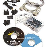
KIT DEMO FOR NE64
Manufacturer
Freescale Semiconductor
Datasheet
1.DEMO9S12NE64.pdf
(28 pages)
Specifications of DEMO9S12NE64
Mfg Application Notes
MC9S12NE64 Integrated Ethernet Controller Implementing an Ethernet Interface with the MC9S12NE64 Web Server Development with MC9S12NE64 and Open TCP
Processor To Be Evaluated
MC9S12NE64
Data Bus Width
16 bit
Interface Type
RS-232
Lead Free Status / RoHS Status
Contains lead / RoHS non-compliant


3.4 BDM Connector J3
3.5 Power Connector J52
Freescale Semiconductor
Pin
3, 5
1
2
4
6
RESET_B
BKGD
P3_3V
Label
GND
NC
Connector J3 is the BDM connector. Figure 3-3 and Table 3-3 give the pin
assignments and signal descriptions for this connector. You can connect
hardware such as P&E’s BDM Multilink to this connector for debugging
purposes.
Table 3-3 BDM Connector J3 Signal Descriptions
Connector J52 is the PWR connector. Figure 3-4 and Table 3-4 give the pin
assignments and signal descriptions for this connector. This connector accepts
a center positive barrell type power plug with an outside diameter of 5.5mm
and an inside diameter of 2.1mm. The power circuit accepts input voltages
from 6 VDC to 12 VDC and currents up to 0.75 amps.
Background pin used as a pseudo-open-drain pin for background debug
communication
GROUND
No connection
Active low bidirectional control signal that acts as an input to initialize the
MCU to a knownstart-up state
3.3 VDC supplied from the DEMO9S12NE64
DEMO9S12NE64 User’s Manual, Rev. 0.7
Figure 3-3 BDM Connector J3 Pin Assignments
BKGD 1
NC1 3
NC2 5
• •
• •
• •
J3
Signal
2
4
6
GND
RESET_B
P3_3V
Support Information
23
Related parts for DEMO9S12NE64
Image
Part Number
Description
Manufacturer
Datasheet
Request
R

Part Number:
Description:
Manufacturer:
Freescale Semiconductor, Inc
Datasheet:
Part Number:
Description:
Manufacturer:
Freescale Semiconductor, Inc
Datasheet:
Part Number:
Description:
Manufacturer:
Freescale Semiconductor, Inc
Datasheet:
Part Number:
Description:
Manufacturer:
Freescale Semiconductor, Inc
Datasheet:
Part Number:
Description:
Manufacturer:
Freescale Semiconductor, Inc
Datasheet:
Part Number:
Description:
Manufacturer:
Freescale Semiconductor, Inc
Datasheet:
Part Number:
Description:
Manufacturer:
Freescale Semiconductor, Inc
Datasheet:
Part Number:
Description:
Manufacturer:
Freescale Semiconductor, Inc
Datasheet:
Part Number:
Description:
Manufacturer:
Freescale Semiconductor, Inc
Datasheet:
Part Number:
Description:
Manufacturer:
Freescale Semiconductor, Inc
Datasheet:
Part Number:
Description:
Manufacturer:
Freescale Semiconductor, Inc
Datasheet:
Part Number:
Description:
Manufacturer:
Freescale Semiconductor, Inc
Datasheet:
Part Number:
Description:
Manufacturer:
Freescale Semiconductor, Inc
Datasheet:
Part Number:
Description:
Manufacturer:
Freescale Semiconductor, Inc
Datasheet:
Part Number:
Description:
Manufacturer:
Freescale Semiconductor, Inc
Datasheet: