G32A-A10-VD DC5-24 Omron, G32A-A10-VD DC5-24 Datasheet - Page 7
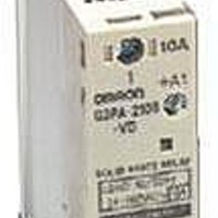
G32A-A10-VD DC5-24
Manufacturer Part Number
G32A-A10-VD DC5-24
Description
REPLACEMENT POWER CARTRIDGE 10A
Manufacturer
Omron
Series
G3PAr
Specifications of G32A-A10-VD DC5-24
Accessory Type
Power Device Cartridge
Control Voltage Range
19 VAC to 264 VAC
Load Voltage Rating
264 V
Load Current Rating
10 A
Output Device
Triac
Relay Type
Solid State
Input Type
DC
Output Type
AC
Input Voltage (max)
30V
Output Voltage (max)
264V
Input Current (max)
7mA
Output Current
10A
Isolation Voltage
4kV
Mounting
Din-Rail
Operating Temp Range
-30C to 80C
Operating Temperature Classification
Commercial
Rad Hardened
No
For Use With/related Products
G3PA Series
For Use With
G3PA-210B-VDDC5-24 - RELAY SSR SPST 10A 24VDC DIN MT
Lead Free Status / RoHS Status
Lead free / RoHS Compliant
Color
-
Lead Free Status / Rohs Status
Lead free / RoHS Compliant
Other names
G32A-A10-VDDC5-24
G32AA10VDDC524
G32AA10VDDC524NC
G32AA10VDDC524
G32AA10VDDC524NC


3. Insert the cartridge into the opening of the G3PA so that side A
■ Linking Terminal Connection
• Connecting with linking terminal for G3PA-210B(L)-VD, -220B(L)-
VD, -240B(L)-VD and G3PA-420B-VD(-2), G3PA-430B-VD(-2).
and side B are even.
1. When SSRs are close
mounted, loosen the
M3.5 Sems screw and
flip the linking terminal
down.
SSR1
When the temperature indicator has turned from pink to red, the G32-A-A Power Device Cartridge
may have malfunctioned, in which case the cartridge must be replaced with a new one.
Connect the terminal with power off.
Refer to the instruction manual for
the G32A-A Power Device Cartridge
to replace the G3PA's triac part.
SSR2
Linking terminal
Linking terminal
2. Insert the linking
Side A
Side B
terminal securely
into the center of
the screw and
tighten the screw.
SSR1
SSR2
4. Tighten the screws on both the corners with a tightening torque of
5. Tighten the screws on both the sides with a tightening torque of
6. Attach the terminal cover.
7. Switch on the power and check the G3PA to be sure it works
• Connecting with linking terminal for G32A.
0.59 to 0.78 N·m.
0.59 to 0.78 N·m.
properly.
1. When SSR are close
SSR
G3PA-420B-VD
mounted, loosen the
M3.5 Sems screw on
the G32A and flip the
linking terminal down.
G32A Unit
Use the terminal cover to prevent accidents
due to electric shock.
Linking
terminal
Linking
terminal
* The cover will not fit if
2. Insert the linking terminal
SSR
the terminal protrudes.
securely into the center
of the screw and tighten
the screw. Ensure that
the linking terminal does
not protrude.
G32A Unit
G3PA
*
7
Related parts for G32A-A10-VD DC5-24
Image
Part Number
Description
Manufacturer
Datasheet
Request
R

Part Number:
Description:
G6S-2GLow Signal Relay
Manufacturer:
Omron Corporation
Datasheet:
Part Number:
Description:
Compact, Low-cost, SSR Switching 5 to 20 A
Manufacturer:
Omron Corporation
Datasheet:
Part Number:
Description:
Manufacturer:
Omron Corporation
Datasheet:
Part Number:
Description:
Manufacturer:
Omron Corporation
Datasheet:
Part Number:
Description:
Manufacturer:
Omron Corporation
Datasheet:
Part Number:
Description:
Manufacturer:
Omron Corporation
Datasheet:
Part Number:
Description:
Manufacturer:
Omron Corporation
Datasheet:
Part Number:
Description:
Manufacturer:
Omron Corporation
Datasheet: