HC4-HP-AC115V Panasonic Electric Works, HC4-HP-AC115V Datasheet - Page 18
HC4-HP-AC115V
Manufacturer Part Number
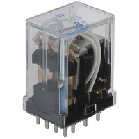
HC4-HP-AC115V
Description
RELAY POWER 5A 115VAC PCB
Manufacturer
Panasonic Electric Works
Series
HCr
Type
General Purpose Relayr
Specifications of HC4-HP-AC115V
Relay Type
General Purpose
Contact Form
4PDT (4 Form C)
Contact Rating (current)
5A
Switching Voltage
250VAC
Coil Type
Standard
Coil Current
11.4mA
Coil Voltage
115VAC
Turn On Voltage (max)
92 VAC
Turn Off Voltage (min)
34.5 VAC
Mounting Type
Through Hole
Termination Style
PC Pin
Circuit
4PDT (4 Form C)
Contact Rating @ Voltage
5A @ 250VAC
Control On Voltage (max)
92 VAC
Control Off Voltage (min)
34.5 VAC
Relay Construction
Non-Latching
Contact Arrangement
4PDT
Coil Voltage Ac
115V
Voltage Rating (vac)
250V
Maximum Power Rating
1.25KVA
Operate Time
20ms
Contact Current Rating
5A
Contact Material
Silver Nickel/Gold Clad
Coil Suppression Diode
No
Push To Test Button
No
Led Indicator
No
Seal
Unsealed
Product Height (mm)
36.7mm
Product Depth (mm)
20.8mm
Product Length (mm)
27.2mm
Operating Temp Range
-50C to 70C
Pin Count
14
Mounting Style
Through Hole
Package / Case
Dust Cover
Lead Free Status / RoHS Status
Lead free / RoHS Compliant
Other names
255-1632
Available stocks
Company
Part Number
Manufacturer
Quantity
Price
Company:

Part Number:
HC4-HP-AC115V
Manufacturer:
PANASONIC
Quantity:
12 000
Company:
Part Number:
HC4-HP-AC115V 110/120V
Manufacturer:
PANASONIC
Quantity:
12 000
Company:
Part Number:
HC4-HP-AC115V/110V
Manufacturer:
PANASONIC
Quantity:
12 000


HC
NOTES
1. Amber sealed type
When mounting TM types, use washers
to prevent damage or distortion to the
polycarbonate cover. When tightening
fixing screws, the optimum torque range
should be 0.294 to 0.49 N·m, (3 to 5
kgf·cm). If screws are over tightened, the
cover may distort, resulting in poor
sealing. Moreover, to prevent loosening,
use washers.
2. Keep relay
1) The schematic differs from that in the
standard type 4 Form C HC relay. Follow
the schematic on the cover sticker.
2) Conform with the schematic for the DC
type, which has a polarized coil.
For Cautions for Use.
HC with
diode type
(For DC)
HC with
CR circuit
Item
1 Form C
2 Form C
3 Form C
4 Form C
4 Form C twin
1 Form C
2 Form C
3 Form C
4 Form C
4 Form C twin
E43028
E43028
E43028
E43028
E43149
E43028
E43028
E43028
E43028
E43149
File No.
UL/C-UL (Recognized)
10A 250V AC
1
3A 30V DC
7A 250V AC
1
3A 30V DC
7A 250V AC
1
3A 30V DC
5A 250V AC
1
3A 30V DC
3A 250V AC
3A 30V DC
10A 250V AC
1
3A 30V DC
7A 250V AC
1
3A 30V DC
7A 250V AC
1
3A 30V DC
5A 250V AC
1
3A 30V DC
3A 250V AC
3A 30V DC
/
/
/
/
/
/
/
/
3
6
6
10
3
6
6
10
HP 125, 250V AC
HP 125, 250V AC
HP 125, 250V AC
HP 125, 250V AC
HP 125, 250V AC
HP 125, 250V AC
HP 125, 250V AC
HP 125, 250V AC
Contact rating
All Rights Reserved © COPYRIGHT Panasonic Electric Works Co., Ltd.
LR26550
etc.
LR26550
etc.
LR26550
etc.
LR26550
etc.
LR26550
etc.
LR26550
etc.
LR26550
etc.
LR26550
etc.
LR26550
etc.
LR26550
etc.
File No.
3) Because retention characteristics vary
according to the waveform of the voltage
applied to the coil, do your best to avoid
capacitor driving.
In capacitor driving, use a capacitor of
300 F or more.
4) Ensure that the minimum pulse width
of voltage applied to coil is greater than
150 ms.
3. Diode characteristics
1) Reverse breakdown voltage: 1,000 V
2) Forward current: 1 A
4. Diode and CR built-in type
Since the diode and CR inside the relay
coil are designed to absorb the counter
emf, the element may be damaged if a
CSA (Certified)
10A 250V AC
1
3A 30V DC
7A 250V AC
1
3A 30V DC
7A 250V AC
1
3A 30V DC
5A 250V AC
1
3A 30V DC
3A 250V AC
3A 30V DC
10A 250V AC
1
3A 30V DC
7A 250V AC
1
3A 30V DC
7A 250V AC
1
3A 30V DC
5A 250V AC
1
3A 30V DC
3A 250V AC
3A 30V DC
/
/
/
/
/
/
/
/
3
6
6
10
3
6
6
10
HP 125, 250V AC
HP 125, 250V AC
HP 125, 250V AC
HP 125, 250V AC
HP 125, 250V AC
HP 125, 250V AC
HP 125, 250V AC
HP 125, 250V AC
Contact rating
File No.
—
—
—
—
—
—
—
—
—
—
VDE (Certified)
Contact rating
—
—
—
—
—
—
—
—
—
—
large surge, etc., is applied to the diode
and CR.
If there is the possibility of a large surge
voltage from the outside, please
implement measures to absorb it.
5. Please connect DC coil types with
LED and built-in diode correctly by
verifying the coil polarity (“+” and “–
”). Connecting with reverse polarity
will cause the LED not to light and
damage the built-in diode due to its
specification.
File No.
—
—
—
—
—
—
—
—
—
—
TV rating (UL/CSA)
Rating
—
—
—
—
—
—
—
—
—
—
Remarks
Related parts for HC4-HP-AC115V
Image
Part Number
Description
Manufacturer
Datasheet
Request
R

Part Number:
Description:
RELAY PWR 5A 4PDT 24VDC PCB
Manufacturer:
Panasonic Electric Works
Datasheet:

Part Number:
Description:
RELAY PWR 4PDT 5A 100VAC PCB
Manufacturer:
Panasonic Electric Works
Datasheet:

Part Number:
Description:
RELAY PWR 5A 4PDT 12VDC PCB
Manufacturer:
Panasonic Electric Works
Datasheet:

Part Number:
Description:
RELAY PWR 5A 4PDT 115VAC VDE PCB
Manufacturer:
Panasonic Electric Works
Datasheet:
Part Number:
Description:
RELAY PWR 5A 4PDT 12VAC PCB
Manufacturer:
Panasonic Electric Works
Datasheet:
Part Number:
Description:
RELAY PWR 5A 4PDT 240VAC PCB
Manufacturer:
Panasonic Electric Works
Datasheet:
Part Number:
Description:
RELAY PWR 5A 4PDT 240VAC VDE PCB
Manufacturer:
Panasonic Electric Works
Datasheet:
Part Number:
Description:
RELAY PWR 5A 4PDT 24VAC PCB
Manufacturer:
Panasonic Electric Works
Datasheet:
Part Number:
Description:
RELAY PWR 5A 4PDT 48VAC PCB
Manufacturer:
Panasonic Electric Works
Datasheet:
Part Number:
Description:
RELAY PWR 5A 4PDT 110VDC PCB
Manufacturer:
Panasonic Electric Works
Datasheet:

Part Number:
Description:
CONN SOCKET P4 .4MM 50POS SMD
Manufacturer:
Panasonic Electric Works
Datasheet:
Part Number:
Description:
CONN SOCKET .8MM 16POS SMD
Manufacturer:
Panasonic Electric Works
Datasheet:
Part Number:
Description:
CONN HEADER .8MM 16POS SMD
Manufacturer:
Panasonic Electric Works
Datasheet:
Part Number:
Description:
CONN SOCKET .8MM 20POS SMD
Manufacturer:
Panasonic Electric Works
Datasheet:
Part Number:
Description:
CONN SOCKET .8MM 20POS SMD
Manufacturer:
Panasonic Electric Works
Datasheet: