HC4-HP-AC115V Panasonic Electric Works, HC4-HP-AC115V Datasheet - Page 8
HC4-HP-AC115V
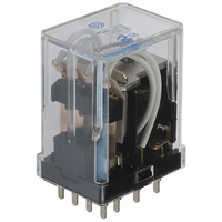
Manufacturer Part Number
HC4-HP-AC115V
Description
RELAY POWER 5A 115VAC PCB
Manufacturer
Panasonic Electric Works
Series
HCr
Type
General Purpose Relayr
Specifications of HC4-HP-AC115V
Relay Type
General Purpose
Contact Form
4PDT (4 Form C)
Contact Rating (current)
5A
Switching Voltage
250VAC
Coil Type
Standard
Coil Current
11.4mA
Coil Voltage
115VAC
Turn On Voltage (max)
92 VAC
Turn Off Voltage (min)
34.5 VAC
Mounting Type
Through Hole
Termination Style
PC Pin
Circuit
4PDT (4 Form C)
Contact Rating @ Voltage
5A @ 250VAC
Control On Voltage (max)
92 VAC
Control Off Voltage (min)
34.5 VAC
Relay Construction
Non-Latching
Contact Arrangement
4PDT
Coil Voltage Ac
115V
Voltage Rating (vac)
250V
Maximum Power Rating
1.25KVA
Operate Time
20ms
Contact Current Rating
5A
Contact Material
Silver Nickel/Gold Clad
Coil Suppression Diode
No
Push To Test Button
No
Led Indicator
No
Seal
Unsealed
Product Height (mm)
36.7mm
Product Depth (mm)
20.8mm
Product Length (mm)
27.2mm
Operating Temp Range
-50C to 70C
Pin Count
14
Mounting Style
Through Hole
Package / Case
Dust Cover
Lead Free Status / RoHS Status
Lead free / RoHS Compliant
Other names
255-1632
Available stocks
Company
Part Number
Manufacturer
Quantity
Price
Company:

Part Number:
HC4-HP-AC115V
Manufacturer:
PANASONIC
Quantity:
12 000
Company:
Part Number:
HC4-HP-AC115V 110/120V
Manufacturer:
PANASONIC
Quantity:
12 000
Company:
Part Number:
HC4-HP-AC115V/110V
Manufacturer:
PANASONIC
Quantity:
12 000


HC
(2) DC coils
Notes: 1. The coil resistance for DC operation is the value measured when the coil temperature is 20 C
2) Specifications
Notes: *1. This value can change due to the switching frequency, environmental conditions and desired reliability level, therefore it is recommended to check this with the
Contact
Rating
Electrical
characteristics
Mechanical
characteristics
Expected life
Conditions
Unit weight
Characteristics
Standard
Type
2. The relay operates in a range of 80% to 110% V of the voltage rating, but ideally, in consideration of temporary voltage fluctuations, it should be operated at the
3. For use with 200 V DC, connect a 10 K (5W) resistor, in series, to the 100 V DC relay.
4. The maximum applied voltage is the maximum voltage fluctuation value for the coil power supply. This value is not a permissible value for continuous operation.
*2. For the AC coil types, the operate/release time will differ depending on the phase.
*3. The upper limit of the ambient temperature is the maximum temperature that can satisfy the coil temperature rise value. Refer to Usage, transport and storage
rated voltage.
(This value differs depending on the ambient temperature. Please contact us for details.)
actual load.
conditions in NOTES.
100/110V DC
Nominal coil
Arrangement
Contact resistance (Initial)
Contact material
Nominal switching capacity
(resistive load)
Max. switching power
(resistive load)
Max. switching voltage
Max. switching current
Nominal operating power
Min. switching capacity
(Reference value)*
Insulation resistance (Initial)
Breakdown
voltage
(Initial)
Temperature rise (coil)
(at 70 C
Operate time (at 20 C
Release time (at 20 C
Shock
resistance
Vibration
resistance
Mechanical
Electrical
Conditions for operation,
transport and storage*
Max. Operating speed
12V DC
24V DC
48V DC
voltage
6V DC
158
F)
Item
80%V or less of
nominal voltage
Pick-up voltage
Between open
contacts
Between contact
sets
Between contact
and coil
Functional
Destructive
Functional
Destructive
(at 20 C
1
(Initial)
3
68
68
68
F)*
F)*
2
2
F)
All Rights Reserved © COPYRIGHT Panasonic Electric Works Co., Ltd.
Ambient temperature: –50 C to +70 C
(at 20 times/min.)
Drop-out voltage
10%V or more of
nominal voltage
(at 20 C
10A 250V AC
resistive load
Min. 2 10
1 Form C
2,500VA
(Initial)
Max. 20ms (Nominal coil voltage applied to the coil, excluding contact bounce time.) (without diode)
10A
Min. 1,000M (at 500V DC) Measurement at same location as “Breakdown voltage” section.
68
Min. 5 10
5
Max. 20ms (Nominal coil voltage applied to the coil, excluding contact bounce time.)
F)
Ag alloy (cd free) + Au flash
Min. 196 m/s
Humidity: 5 to 85% R.H. (Not freezing and condensing at low temperature)
Nominal coil current
7
: AC coil type (at 180 times/min.); Min. 10
10 to 55 Hz at double amplitude of 1 mm (Detection time: 10 s.)
(at 20 times/min.)
(at 20 C
Max. 80 C
resistive load
7A 250V AC
Min. 2 10
10/11mA
2 Form C
1,750VA
18.5mA
[ 10%]
150mA
AC (50Hz): 1.3VA, AC (60Hz): 1.2VA, DC: 0.9 to 1.1W
75mA
37mA
Min. 980 m/s
7A
2
2,000 Vrms for 1min. (Detection current: 10mA.)
700 Vrms for 1min. (Detection current: 10mA.)
700 Vrms for 1min. (Detection current: 10mA.)
(Half-wave pulse of sine wave: 11 ms; detection time: 10 s.)
68
Max. 30 m (By voltage drop 6 V DC 1A)
10 to 55 Hz at double amplitude of 2 mm
176 F
5
–58 F to +158 F
F)
1mA 1V DC
20 times/min. (at max. rating)
2
(By resistive method, nominal coil voltage)
(Half-wave pulse of sine wave: 6 ms.)
Approx. 30g
(at 20 times/min.)
68
Coil resistance
(at 20 C
Specifications
resistive load
7A 250V AC
10,000
F. Compensate 0.4% for every 1 C change in temperature.
3 Form C
[ 10%]
2,600
1,750VA
250VAC
Min. 10
160
650
40
(without LED); –50 C to +60 C
7A
68
1.06 oz
5
F)
8
: DC coil type (at 180 times/min.)
Nominal operating
(at 20 times/min.)
resistive load
5A 250V AC
Min. 2 10
4 Form C
power
1,250VA
0.9W
1.0W
5A
AgNi type + Au clad
5
–58 F to +140 F
Max. applied voltage
(at 20 times/min.)
(at 70 C
nominal voltage
4 Form C (twin)
100 A 1V DC
resistive load
3A 250V AC
110%V of
Min. 2 10
750VA
3A
(with LED)
158
5
F)
Related parts for HC4-HP-AC115V
Image
Part Number
Description
Manufacturer
Datasheet
Request
R

Part Number:
Description:
RELAY PWR 5A 4PDT 24VDC PCB
Manufacturer:
Panasonic Electric Works
Datasheet:

Part Number:
Description:
RELAY PWR 4PDT 5A 100VAC PCB
Manufacturer:
Panasonic Electric Works
Datasheet:

Part Number:
Description:
RELAY PWR 5A 4PDT 12VDC PCB
Manufacturer:
Panasonic Electric Works
Datasheet:

Part Number:
Description:
RELAY PWR 5A 4PDT 115VAC VDE PCB
Manufacturer:
Panasonic Electric Works
Datasheet:
Part Number:
Description:
RELAY PWR 5A 4PDT 12VAC PCB
Manufacturer:
Panasonic Electric Works
Datasheet:
Part Number:
Description:
RELAY PWR 5A 4PDT 240VAC PCB
Manufacturer:
Panasonic Electric Works
Datasheet:
Part Number:
Description:
RELAY PWR 5A 4PDT 240VAC VDE PCB
Manufacturer:
Panasonic Electric Works
Datasheet:
Part Number:
Description:
RELAY PWR 5A 4PDT 24VAC PCB
Manufacturer:
Panasonic Electric Works
Datasheet:
Part Number:
Description:
RELAY PWR 5A 4PDT 48VAC PCB
Manufacturer:
Panasonic Electric Works
Datasheet:
Part Number:
Description:
RELAY PWR 5A 4PDT 110VDC PCB
Manufacturer:
Panasonic Electric Works
Datasheet:

Part Number:
Description:
CONN SOCKET P4 .4MM 50POS SMD
Manufacturer:
Panasonic Electric Works
Datasheet:
Part Number:
Description:
CONN SOCKET .8MM 16POS SMD
Manufacturer:
Panasonic Electric Works
Datasheet:
Part Number:
Description:
CONN HEADER .8MM 16POS SMD
Manufacturer:
Panasonic Electric Works
Datasheet:
Part Number:
Description:
CONN SOCKET .8MM 20POS SMD
Manufacturer:
Panasonic Electric Works
Datasheet:
Part Number:
Description:
CONN SOCKET .8MM 20POS SMD
Manufacturer:
Panasonic Electric Works
Datasheet: