G2R-1-S AC240(S) Omron, G2R-1-S AC240(S) Datasheet - Page 24
G2R-1-S AC240(S)
Manufacturer Part Number
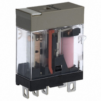
G2R-1-S AC240(S)
Description
RELAY GP SPDT 240VAC PLUG-IN
Manufacturer
Omron
Series
G2RSr
Datasheets
1.G2R-1A-E-DC12.pdf
(30 pages)
2.G2R-1A-E-DC12.pdf
(14 pages)
3.G2R-1-S_DC12S.pdf
(12 pages)
Specifications of G2R-1-S AC240(S)
Relay Type
General Purpose
Contact Form
SPDT (1 Form C)
Contact Rating (current)
10A
Switching Voltage
440VAC, 125VDC - Max
Coil Type
Standard
Coil Current
3.2mA
Coil Voltage
240VAC
Turn On Voltage (max)
192 VAC
Turn Off Voltage (min)
72 VAC
Mounting Type
Socket
Termination Style
Quick Connect - .187" (4.7mm)
Circuit
SPDT (1 Form C)
Contact Rating @ Voltage
10A @ 250VAC
Control On Voltage (max)
192 VAC
Control Off Voltage (min)
72 VAC
Contact Rating
10 A
Contact Termination
Pin
Mounting Style
Plug-In
Power Consumption
0.9 VA
Contact Material
Silver Alloy
Coil Resistance
30.36 K Ohms
Lead Free Status / RoHS Status
Lead free / RoHS Compliant
Other names
G2R-1-S-AC240(S)
G2R-1S-AC240(S)
G2R1SAC240S
Z2227
G2R-1S-AC240(S)
G2R1SAC240S
Z2227


■ Driving by IC
An IC on which multiple driving transistors are integrated is available.
The designing of the circuit or PCB to drive multiple relays, a small-
size solenoid, or a small-size lamp can be simplified by using this IC.
Consult the manufacturer of the IC for details. For V
description of the related voltage and surge suppressor.
Dimensions Connection (Top view)
Equivalent circuit
■ Driving by TTL
TTLs can be divided into two types by classification of the output:
totem-pole and open-collector outputs. Connection of each type of
TTL is described below.
Use a diode as surge suppressor.
In the specifications of some ICs, such a phrase as “fan-out 10” may
be used in place of the legend I
TTLs can be connected in parallel. In terms of current, fan-out 1
equals 1.6 mA. Hence,
Fan-out n = 1.6 x n (mA)
1. To drive a relay by the totem-pole output of a TTL, these condi-
24
tions must be satisfied:
• I
• I
• Minimum supply voltage (4.75 V) – Maximum V
resistance.
(%)/Coil resistance
put voltage) > Lower-limit value of pickup voltage (Refer to Driv-
ing by Transistor)
OL
OH
(high-level output current) < Rated current x pickup voltage
(low-level output current) > Maximum supply voltage/Coil
Electromechanical Relays
GND
OL
. This denotes that 10 standard
I: Input (Base)
O: Output (Collector)
GND: (Common Emitter)
Technical Information
OL
GND
CE
(low-level out-
, refer to the
Totem-pole output
2. To drive a relay with open-collector output type TTL, a degree of
Open-collector output
The above description of the standard TTL is applicable when using
S, H, and LS type TTLs.
■ Driving by Other Switching
Consult the manufacturer of the switching device. The upper- and
lower-limit values of the pickup voltage can be determined in the
same manner as described in Upper-limit Pickup Voltage and Lower-
limit Pickup Voltage.
Example of Driving by SCR
freedom is allowed in the ratings of the relay coil. However, these,
conditions must be satisfied:
• I
• I
• V
• V
Devices
by Transistor.)
to Driving by Transistor.)
OL
OH
O
OL
> Maximum supply voltage to the relay coil/Coil resistance
= Dielectric strength of the output transistor (Refer to Driving
< Rated current x pickup voltage (%)/200
= Collector emitter voltage V
CE
of the output transistor (Refer
Related parts for G2R-1-S AC240(S)
Image
Part Number
Description
Manufacturer
Datasheet
Request
R

Part Number:
Description:
POWER RELAY, SPDT, 120VAC, 10A, PLUG IN
Manufacturer:
Omron
Datasheet:

Part Number:
Description:
Relay
Manufacturer:
Omron
Datasheet:

Part Number:
Description:
RELAY; E-MECH; POWER; SPDT; CUR-RTG 10A; CTRL-V 24DC; VOL-RTG 250/30AC/DC; SOCKET MNT
Manufacturer:
Omron Automation
Datasheet:
Part Number:
Description:
RELAY; E-MECH; POWER; SPDT; CUR-RTG 10A; CTRL-V 120AC; VOL-RTG 250/30AC/DC; SOCKET MNT
Manufacturer:
Omron Automation
Datasheet:
Part Number:
Description:
RELAY; E-MECH; POWER; SPDT; CUR-RTG 10A; CTRL-V 12DC; VOL-RTG 250/30AC/DC; SOCKET MNT
Manufacturer:
Omron Automation
Datasheet:
Part Number:
Description:
RELAY; E-MECH; POWER; SPDT; CUR-RTG 10A; CTRL-V 24AC; VOL-RTG 250/30AC/DC; SOCKET MNT
Manufacturer:
Omron Automation
Datasheet:
Part Number:
Description:
RELAY
Manufacturer:
Omron Automation
Datasheet:

Part Number:
Description:
Relay
Manufacturer:
Omron
Datasheet:
Part Number:
Description:
Relay
Manufacturer:
Omron
Datasheet:
Part Number:
Description:
Relay
Manufacturer:
Omron
Datasheet:
Part Number:
Description:
Relay
Manufacturer:
Omron
Datasheet:
Part Number:
Description:
Relay
Manufacturer:
Omron
Datasheet:
Part Number:
Description:
Relay
Manufacturer:
Omron
Datasheet:
Part Number:
Description:
Relay
Manufacturer:
Omron
Datasheet: