P7MF-06 Omron, P7MF-06 Datasheet
P7MF-06
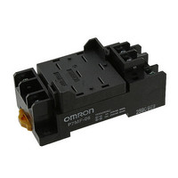
Specifications of P7MF-06
Z2990
Available stocks


Related parts for P7MF-06


P7MF-06 Summary of contents
Page 1
... Note: 1. The P7M-06P, P7MF-06, and P7MF-06-D can be used with models for DC loads with an SPST-NO or SPST-NO/SPST-NC contact form or with models for AC loads with an SPST-NO or SPST-NO/SPST-NC contact form. 2. The P7MF-06-D has a built-in diode and can thus be used only with Relays with DC operating coils. Do not use it with a Relay with an AC operating coil. ...
Page 2
... NO NC Max. switching current NO NC Max. switching capacity NO (reference value) NC Note: These values apply to a switching frequency of 20 times per minute. 2 General Purpose Power Relays SPST-NO MKS1XT(I)(N)-10 Inductive load L DC13 class Double-break --- AgSnIn 5 A, 220 VDC 0.4 A, 220 VDC --- ...
Page 3
... Hz, 1.5-mm double amplitude 2 Destruction: 1,000 m/s when relay is properly mounted into P7M-06P PCB socket 2 500m/s when relay is properly mounted into P7MF-06(-D) socket 2 Malfunction 100 m/s 1,000,000 operations min. (at 18,000 operations/hr VDC −40°C to 60°C (with no icing or condensation) Note: The range is −25°C to 60°C for models with built-in operation indicators. ...
Page 4
... Model Coil ratings 12, 24, 48, 110, 220 VDC MKS1XT@-@ 24, 100, 110, 120, 200, 220, 230, 240 VAC MKS2XT@-@ MKS1T@-@ MKS2T@-@ 4 General Purpose Power Relays Contact ratings 10 A, 220 VDC (Resistive 220 VDC L contacts 0.632 0.4 A, 220 VDC L 300 ms 0. 220 VDC (Resistive) ...
Page 5
... AC resistive load resistive load 1 NC 0.1 0. 100 1.000 Switching voltage (V) MKS2XT-11 DC Specification 100 Must operate Number of Relays: 5 voltage Must release voltage - Ambient temperature (°C) MKS2XT@-11 10 220 VDC NO 1 0 100 Load time constant (ms) MKS-X General Purpose Power Relays 5 ...
Page 6
... A (+) B (− Note: 1. Wire properly using the correct coil polarity. 2. The contact terminals on Models for DC Loads have polarity. Wire properly using the correct polarity. 6 General Purpose Power Relays 34.5 max. 0.8 44 max. 7.3 3.5 34.5 max. 0.8 44 max. 7.3 MKS2XT-11 MKS2XTI-11 ...
Page 7
... Terminal Arrangement/Internal Connections (TOP View) P7MF-06 35.5 Note: 1. The internal connections diagram is for the MKS2(X)T@@-11 The P7MF-06-D has polarity. Be careful to wire with the correct polarity. General Purpose Power Relays PCB Mounting Holes (Bottom View 11.05 11.05 Mounting Holes ...
Page 8
... Hold-down Clip PYC-A2 One Set (Two Clips) 5 max. 42.8 4.5 4.5 1.2 Note: The minimum order for the PYC-A2 is ten clips. Socket Mounting Height P7M-06P P7MF-06 P7MF-06-D 8 General Purpose Power Relays 64 MK-S(X) 61 MK-S( MKS ...
Page 9
... Do not install the Relay near IC cards or other items that may be adversely affected by magnetism. Usage Use the Relay mounted in the P7M-06P or P7MF-06(-D) Socket. Test Button • Turn OFF the power supply before operating the test button. Always return the test button to the original position after you use it. ...
Page 10
... MEMO 10 General Purpose Power Relays MKS-X ...
Page 11
... Seller within 30 days of receipt of shipment. III. PRECAUTIONS 1. Suitability THE BUYER’S SOLE RESPOINSIBILITY TO ENSURE THAT ANY OMRON PRODUCT IS FIT AND SUFFICIENT FOR USE IN A MOTORIZED VEHICLE APPLICATION. BUYER SHALL BE SOLELY RESPONSIBLE FOR DETERMINING APPROPRIATENESS OF THE PARTICULAR PRODUCT WITH RESPECT TO THE BUYER’ ...
Page 12
... THE OMRON PRODUCT IS PROPERLY RATED AND INSTALLED FOR THE INTENDED USE WITHIN THE OVERALL EQUIPMENT OR SYSTEM. Complete “Terms and Conditions of Sale” for product purchase and use are on Omron’s website at http://www.components.omron.com – under the “About Us” tab, in the Legal Matters section. ...