S-PS Panasonic Electric Works, S-PS Datasheet

ACCY RELAY SOCKET FOR S SERIES

S-PS

Manufacturer Part Number
S-PS
Description
ACCY RELAY SOCKET FOR S SERIES
Manufacturer
Panasonic Electric Works
Series
Sr
Type
Socketr
Datasheets

Specifications of S-PS

Number Of Positions
12
Mounting Type
Through Hole
Termination Style
PC Pin
For Use With/related Products
S Series
For Use With
S4EB-L2-6V - RELAY LATCH 4A 6VDC AMBER PCB255-2835 - RELAY LATCH 4A 5VDC AMBER PCBS4EB-L2-24V - RELAY LATCH 4A 24VDC AMBER PCBS4EB-L2-12V - RELAY LATCH 4A 12VDC AMBER PCBS4EB-L-3V - RELAY LATCH 4A 3VDC AMBER PCBS4EB-9V - RELAY 4A 9VDC AMBER SEAL PCBS4EB-6V - RELAY 4A 6VDC AMBER SEAL PCB255-2252 - RELAY 4A 5VDC AMBER SEAL PCBS4EB-48V - RELAY 4A 48VDC AMBER SEAL PCBS3EB-L2-5V - RELAY LATCH 4PST 4A 5VDC PCBS3EB-L2-12V - RELAY LATCH 4PST 4A 12VDC PCB255-1889 - RELAY 4A 4PST AMBER 5VDC PCBS3EB-48V - RELAY 4A 4PST 48VDC AMBER PCB255-1888 - RELAY 4A 4PST AMBER 24VDC PCB255-1887 - RELAY 4A 4PST AMBER 12VDC PCBS2EB-L2-6V - RELAY LATCH 4A 6VDC AMBER PCBS2EB-L2-48V - RELAY LATCH 4A 48VDC AMBER PCBS2EB-L2-3V - RELAY LATCH 4A 3VDC AMBER PCB255-2251 - RELAY LATCH 4A 24VDC AMBER PCBS2EB-L-12V - RELAY LATCH 4A 12VDC AMBER PCBS2EB-6V - RELAY 4A 6VDC AMBER SEALED PCBS2EB-48V - RELAY 4A 48VDC AMBER SEALED PCBS2EB-3V - RELAY 4A 3VDC AMBER SEALED PCB255-1744 - RELAY POWER 4A 24VDC PCB255-2834 - RELAY POWER 4A 12VDC PCB255-2833 - RELAY POWER LATCHING 4A 5VDC PCB255-1741 - RELAY POWER 4A 5VDC PCB255-1739 - RELAY POWER 4A 12VDC PCB255-1489 - RELAY PWR LATCHING 4A 12VDC PCB255-1740 - RELAY POWER 4A 24VDC PCB
Lead Free Status / RoHS Status
Lead free / RoHS Compliant
Other names
255-1751
S
FEATURES
1. Compact with high sensitivity
4-GAP BALANCED ARMATURE MECHANISM
1. Armature mechanism has excellent
resistance to vibration and shock
The armature structure enables free
rotation around the armature center of
gravity. Because the mass is maintained
in balance at the fulcrum of the axis of
rotation, large rotational forces do not
occur even if acceleration is applied
along any vector. The mechanism has
proven to have excellent resistance to
vibration and shock. All our S relays are
based on this balanced armature
mechanism, which is able to further
provide many other characteristics.
HOW IT WORKS
1) When current is passed through the
coil, the yoke becomes magnetic and
polarized.
2) At either pole of the armature,
repulsion on one side and attraction on
the other side is caused by the interaction
of the poles and the permanent magnets
of the armature.
Compliance with RoHS Directive
The high-efficiency polarized
electromagnetic circuits of the 4-gap
balanced armature and our exclusive
spring alignment method achieves,
with high-sensitivity in a small
package, a relay that can be directly
controlled by a driver chip.
(single side stable type)
All Rights Reserved © COPYRIGHT Panasonic Electric Works Co., Ltd.
2. Strong resistance to vibration and
3. High reliability and long life
4. Ability to provide wide-ranging
5. Latching types available
6. Wide variety of contact formations
2. High sensitivity and reliability
provided by 4-gap balanced armature
mechanism
As a (polarized) balanced armature, the
S relay armature itself has two
permanent magnets. Presenting four
interfaces, the armature has a 4-gap
structure. As a result, the rotational axis
at either end of the armature is
symmetrical and, in an energized into a
polarized state, the twin magnetic
armature interfaces are subject to
repulsion on one side and attraction on
the other. This mechanism, exclusive to
3) At this time, opening and closing
operates owing to the action of the
simultaneously moulded balanced
armature mechanism, so that when the
force of the contact breaker spring closes
the contact on one side, on the other
side, the balanced armature opens the
contact (2a2b).
2a2b/3a1b/4a 4A polarized
shock
Use of 4G-BA technology realizes
strong resistance to vibration and
shock.
Our application of 4G-BA technology,
along with almost perfectly complete
twin contact, ensures minimal contact
bounce and high reliability.
control
Use of 4G-BA technology with gold-
clad silver alloy contacts in a twin
contact structure enables control
across a broad range from
microcurrents of 100 A 100 mV DC to
4 A 250 V AC.
With 4G-BA technology, as well as
single side stable types, convenient 2
coil latching types for circuit memory
applications are also available.
available
The compact size of the 4G-BA
mechanism enables the provision of
many kinds of package, including
2a2b, 3a1b, and 4a. These meet your
needs across a broad range of
applications.
power relays
7. Low thermal electromotive force
8. DIL terminal array
9. Relays that push the boundaries of
10. Sockets are available.
TYPICAL APPLICATIONS
Telecommunications equipment, data
processing equipment, facsimiles, alarm
equipment, measuring equipment.
Panasoinc Electric Works, provides a
highly efficient polarized magnetic circuit
structure that is both highly sensitive and
has a small form factor. Moreover,
suitability for provision with many types of
contact array and other advantages
promise to make it possible to provide
many of the various characteristics that
are coming to be demanded of relays.
relay
High sensitivity (low power
consumption) is realized by 4G-BA
technology. Separation of the coil and
spring sections has resulted in a relay
with extremely low levels of thermal
electromotive force (approx. 0.3 V).
Deployed to fit a 2.54 mm
grid, the terminals are presented in DIL
arrays which match the printed circuit
board terminal patterns commonly in
international use.
relay efficiency
High-density S relays take you close to
the limits of relay efficiency.
S RELAYS
Attraction
Repulsion
Residual plate
Permanent magnet
Repulsion
Axis
.100 inch
Attraction

Related parts for S-PS

S-PS Summary of contents

Page 1

... All Rights Reserved © COPYRIGHT Panasonic Electric Works Co., Ltd. S RELAYS 7. Low thermal electromotive force relay High sensitivity (low power consumption) is realized by 4G-BA technology ...

Page 2

... Form A Operating function Nil: Single side stable L: 1 coil latching* L2: 2 coil latching Nominal coil voltage (DC 12, 24 Notes coil latching type are manufactured by lot upon receipt of order. 2. Certified by UL and CSA TYPES Contact arrangement Nominal coil voltage Form A 2 Form B 12V DC ...

Page 3

... Max. operating speed Unit weight Notes: *1. This value can change due to the switching frequency, environmental conditions, and desired reliability level, therefore it is recommended to check this with the actual load. *2. The upper limit of the ambient temperature is the maximum temperature that can satisfy the coil temperature rise value. Refer to Usage, transport and storage conditions in NOTES ...

Page 4

... Coil operating power Influence of adjacent mounting Note: When installing an S-relay near another, and there is no effect from an external magnetic field, be sure to leave at least 10 mm .394 inch (1) & (3) relays listed in the catalog. (1) (2) (3) are energized Single side stable ...

Page 5

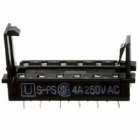
... File No. Contact rating E43028 4A 250V AC 125V AC (FLA1.5A 250V AC (FLA0.75A), 3A 30V NOTES 1. Based on regulations regarding insulation distance, there is a restriction on same-channel load connections between terminals No and well as between No and 10, 11. See the figure below for an example • Between 2, 3 and 4, 5: • ...

Page 6

... Terminal width: 1.3 1.5 0.3 1.5 0.3 1.276 .024 .059 .012 .059 .012 Terminal thickness: 1.2 General tolerance: 0.3 Part No. S- 1,500 Vrms between terminals 150 3 C (302 5.4 F) for 1 hour. Rib Fig. 1 Fig. 2 Fig RELAYS SOCKET ...

Related keywords