S-PS Panasonic Electric Works, S-PS Datasheet - Page 4
S-PS
Manufacturer Part Number
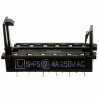
S-PS
Description
ACCY RELAY SOCKET FOR S SERIES
Manufacturer
Panasonic Electric Works
Series
Sr
Type
Socketr
Specifications of S-PS
Number Of Positions
12
Mounting Type
Through Hole
Termination Style
PC Pin
For Use With/related Products
S Series
For Use With
S4EB-L2-6V - RELAY LATCH 4A 6VDC AMBER PCB255-2835 - RELAY LATCH 4A 5VDC AMBER PCBS4EB-L2-24V - RELAY LATCH 4A 24VDC AMBER PCBS4EB-L2-12V - RELAY LATCH 4A 12VDC AMBER PCBS4EB-L-3V - RELAY LATCH 4A 3VDC AMBER PCBS4EB-9V - RELAY 4A 9VDC AMBER SEAL PCBS4EB-6V - RELAY 4A 6VDC AMBER SEAL PCB255-2252 - RELAY 4A 5VDC AMBER SEAL PCBS4EB-48V - RELAY 4A 48VDC AMBER SEAL PCBS3EB-L2-5V - RELAY LATCH 4PST 4A 5VDC PCBS3EB-L2-12V - RELAY LATCH 4PST 4A 12VDC PCB255-1889 - RELAY 4A 4PST AMBER 5VDC PCBS3EB-48V - RELAY 4A 4PST 48VDC AMBER PCB255-1888 - RELAY 4A 4PST AMBER 24VDC PCB255-1887 - RELAY 4A 4PST AMBER 12VDC PCBS2EB-L2-6V - RELAY LATCH 4A 6VDC AMBER PCBS2EB-L2-48V - RELAY LATCH 4A 48VDC AMBER PCBS2EB-L2-3V - RELAY LATCH 4A 3VDC AMBER PCB255-2251 - RELAY LATCH 4A 24VDC AMBER PCBS2EB-L-12V - RELAY LATCH 4A 12VDC AMBER PCBS2EB-6V - RELAY 4A 6VDC AMBER SEALED PCBS2EB-48V - RELAY 4A 48VDC AMBER SEALED PCBS2EB-3V - RELAY 4A 3VDC AMBER SEALED PCB255-1744 - RELAY POWER 4A 24VDC PCB255-2834 - RELAY POWER 4A 12VDC PCB255-2833 - RELAY POWER LATCHING 4A 5VDC PCB255-1741 - RELAY POWER 4A 5VDC PCB255-1739 - RELAY POWER 4A 12VDC PCB255-1489 - RELAY PWR LATCHING 4A 12VDC PCB255-1740 - RELAY POWER 4A 24VDC PCB
Lead Free Status / RoHS Status
Lead free / RoHS Compliant
Other names
255-1751


REFERENCE DATA
1. Maximum switching power
4.-(1) Coil temperature rise
Tested Sample: S4EB-24V, 4 Form A
6. Influence of adjacent mounting
8. Effect from an external magnetic field
1,000
100
100
(1)
10
90
80
70
60
50
40
30
20
10
0
+30
–30
+30
+30
–30
–30
0
0
0
(2)
Single side stable
Single side stable
2 coil latching
0.2
DC resistive load
(3)
0.1
Drop-out voltage
Pick-up voltage
0.4
Coil operating power, W
(1) & (3) relays
are energized
Inter-relay distance, mm
Contact current, A
0.6
50
50
5
Drop-out voltage
G
G
0.8
AC resistive load
1
Pick-up voltage
Pick-up voltage
1.0
Note: When installing an S-relay near another, and there is no effect
4A
0A
All Rights Reserved © COPYRIGHT Panasonic Electric Works Co., Ltd.
10
1.2
from an external magnetic field, be sure to leave at least 10 mm
.394 inch
listed in the catalog.
100
100
10
between relays in order to achieve the performance
+30
–30
2. Life curve
4.-(2) Coil temperature rise
Tested Sample: S4EB-24V, 4 Form A
0
2 coil latching
+30
–30
+30
–30
1,000
0
0
100
500
100
Single side stable
2 coil latching
50
30
10
90
80
70
60
50
40
30
20
10
0
0
Coil operating
power, 0.2 W
1
1
Pick-up voltage
Inter-relay distance, mm
5
2
2
Contact current, A
50
50
Contact current, A
G
G
3
3
Drop-out voltage
Pick-up voltage
Pick-up voltage
125 V AC
(cos = 1.0)
250 V AC
(cos = 1.0)
4
4
10
5
5
100
100
6
3. Contact reliability
Condition: 1V DC, 1mA
Detection level 10
Tasted Sample: S4EB-24V, 10pcs
5. Operate and release time
(Single side stable type)
Tested Sample: S4EB-24V, 10pcs
7. Thermal electromotive force
99.9
99.0
95.0
70.0
50.0
30.0
10.0
200
100
5.0
2.0
1.0
0.5
0.2
0.1
20
18
16
14
12
10
8
6
4
2
0
Max.
Min.
80
Release time
2
Release time (with diode)
4
100
No. of operations, 10
Coil applied voltage, %V
m = 1.6
95% reliability limit:
14.6 million times
(weibul probability paper)
: 79 million time
: 51 million time
1.0
NR-H
6
Minute
Operate time
120
NF relay S relay
8
10
140
7
Max.
Min.
Max.
Min.
10.0
12
S
Related parts for S-PS
Image
Part Number
Description
Manufacturer
Datasheet
Request
R

Part Number:
Description:
Manufacturer:
Panasonic Electric Works
Datasheet:
Part Number:
Description:
Manufacturer:
Panasonic Electric Works
Datasheet:

Part Number:
Description:
CONN SOCKET P4 .4MM 50POS SMD
Manufacturer:
Panasonic Electric Works
Datasheet:
Part Number:
Description:
CONN SOCKET .8MM 16POS SMD
Manufacturer:
Panasonic Electric Works
Datasheet:
Part Number:
Description:
CONN HEADER .8MM 16POS SMD
Manufacturer:
Panasonic Electric Works
Datasheet:
Part Number:
Description:
CONN SOCKET .8MM 20POS SMD
Manufacturer:
Panasonic Electric Works
Datasheet:
Part Number:
Description:
CONN SOCKET .8MM 20POS SMD
Manufacturer:
Panasonic Electric Works
Datasheet:
Part Number:
Description:
CONN HEADER .8MM 20POS SMD
Manufacturer:
Panasonic Electric Works
Datasheet:
Part Number:
Description:
CONN SOCKET .8MM 22POS SMD
Manufacturer:
Panasonic Electric Works
Datasheet:
Part Number:
Description:
CONN SOCKET .8MM 30POS SMD
Manufacturer:
Panasonic Electric Works
Datasheet:
Part Number:
Description:
CONN HEADER .8MM 30POS SMD
Manufacturer:
Panasonic Electric Works
Datasheet:
Part Number:
Description:
CONN SOCKET .8MM 30POS SMD
Manufacturer:
Panasonic Electric Works
Datasheet:
Part Number:
Description:
CONN SOCKET .8MM 30POS SMD
Manufacturer:
Panasonic Electric Works
Datasheet:
Part Number:
Description:
CONN HEADER .8MM 30POS SMD
Manufacturer:
Panasonic Electric Works
Datasheet:
Part Number:
Description:
CONN HEADER BRD/BRD .5MM 60POS
Manufacturer:
Panasonic Electric Works
Datasheet: