27E194 Tyco Electronics, 27E194 Datasheet - Page 3
27E194
Manufacturer Part Number
27E194
Description
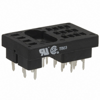
SOCKET 4POLE R10 SERIES
Manufacturer
Tyco Electronics
Series
R10r
Type
Socketr
Specifications of 27E194
Number Of Positions
16
Mounting Type
Through Hole
Termination Style
PC Pin
Features
Grounding Terminal
Accessory Type
Socket
Associated Relay Series
R10
Number Of Poles
4
For Use With/related Products
R10 Series
For Use With
R10-E1Y4-JJ1.0K - RELAY GP 4PDT 3AR10-E1X4-V52 - RELAY DRY CIR 5A PCBR10-E1M4-V2.5K - RELAY DRY CIR 5AR10-E1L4-115V - RELAY DRY CIR 7.5AR10-E1W4-115V - RELAY GP DPDT 7.5A 115VACR10-E1P4-V15.0K - RELAY GP 4PDT 3A 115VDCR10-E1P4-V185 - RELAY GP 4PDT 3A 12VDCR10-E1P4-V700 - RELAY GP 4PDT 3A 24VDCR10-E1P4-115V - RELAY GP 4PDT 3A 115VACR10-E1W4-S1.8K - RELAY GP 4PDT 7.5A 24VDCR10-E1W4-V185 - RELAY GP 4PDT 7.5A 12VDCR10-E1Y4-JJ2.5K - RELAY GP 4PDT 3AR10-E1Y4-J1.0K - RELAY GP 4PDT 3AR10-E1Y4-J2.5K - RELAY GP 4PDT 3AR10-E1W4-V2.5K - RELAY GP 4PDT 7.5A 48VDCR10-E1X4-24V - RELAY GP 4PDT 5A 24VACR10-E1X4-S450 - RELAY GP 4PDT 5A 12VDCR10-E1X4-V15.0K - RELAY GP 4PDT 5A 115VDCR10-E1Z4-115V - RELAY GP 4PDT 2A 115VACR10-E1Z4-J1.0K - RELAY GP 4PDT 2AR10S-E1Y4-J1.0K - RELAY GP 4PDT 3A 40MWR10-E1Z4-V700 - RELAY GP 4PDT 2A 24VDCR10-E1Z4-V185 - RELAY GP 4PDT 2A 12VDCR10-E1Z4-V2.5K - RELAY GP 4PDT 2A 48VDCPB772 - RELAY GP 4P 7.5A 24VDC CVR SLDPB599 - RELAY GP 4PDT 5A 115VAC PNL MNTPB453 - RELAY GP 5A 4PDT 24VDCR10E1Y4J10.0KBULK - GENERAL PURPOSE RELAYPB131 - RELAY GP 5A 4PDT 48VDCPB130 - RELAY GP 5A 4PDT 24VDCPB129 - RELAY GP 5A 4PDT 12VDCPB123 - RELAY GP 3A 4PDT 48VDCPB122 - RELAY GP 3A 4PDT 24VDCPB121 - RELAY GP 3A 4PDT 12VDCPB120 - RELAY GP 3A 4PDT 6VDC
Lead Free Status / RoHS Status
Lead free / RoHS Compliant
Other names
2-1393143-2
PB804
PB804


09-2010, Rev. 0910
www.te.com
© 2010 Tyco Electronics Ltd.
Coil versions, DC coil (continued)
J - sensitive DC current adjustment – R10S types only
2 pole
4 pole
1) Suggested for 5VDC operation
2) Suggested for 12VDC operation
3) Suggested for 24VDC operation
JJ - ultrasensitive DC current adjustment
1 pole
2 pole
4 pole
All figures are given for coil without preenergization, at ambient temperature +23°C.
Coil versions, AC coil (dual coil diode rectified construction)
Standard AC
All figures are given for coil without preenergization, at ambient temperature +23°C.
JJ1.0K
6 and 8 pole
Coil
code
J500
J1.0K
J2.5K
J5.0K
J10.0K
J16.0K
J30.0K
J500
J1.0K
J2.5K
J5.0K
J10.0K
J16.0K
J30.0K
JJ2.5K
JJ5.0K
JJ10.0K
JJ15.0K
JJ30.0K
JJ1.0K
JJ2.5K
JJ5.0K
JJ10.0K
JJ15.0K
JJ30.0K
JJ1.0K
JJ2.5K
JJ5.0K
JJ10.0K
JJ15.0K
JJ30.0K
Coil
code
2 and 4 pole
115V
115V
12V
24V
48V
12V
24V
48V
6V
6V
1)
2)
2)
3)
3)
coil current
Maximum
voltage
mADC
Rated
11.5
11.5
11.5
VAC
115
115
8.3
8.3
8.3
45
28
20
14
45
28
20
14
45
28
20
14
12
24
48
12
24
48
–
–
–
–
–
–
–
–
–
–
–
–
–
–
6
6
Operate
Operate
current
voltage
mADC
18
36
86
18
36
86
VAC
6.3
4.5
2.9
2
1.4
1.2
0.8
9
6.5
4.1
2.9
2
1.4
1.2
4.5
2.9
2.1
1.5
1.2
0.85
6.5
4.1
2.9
2
1.7
1.2
9
5.8
4.1
3
2.4
1.7
5
9
5
9
General Purpose Relays
Industrial Relays
R10 Series Panel Plug-in Relay
Datasheets and product specification ac-
cording to IEC 61810-1 and to be used only
together with the ‘Definitions’ section.
resistance
resistance
Ω±10%
Ω±20%
10000
16000
30000
10000
16000
30000
10000
15000
30000
10000
15000
30000
10000
15000
30000
1000
2500
5000
1000
2500
5000
1000
2500
5000
1000
2500
5000
1000
2500
5000
2000
9000
1400
7500
500
500
120
500
350
Coil
Coil
25
15
90
coil power
Pick-up
mW
20
20
25
20
20
25
20
45
45
45
45
40
35
45
20
25
25
25
25
25
45
45
45
40
45
45
85
85
85
90
85
90
Datasheets and product data is subject to the
terms of the disclaimer and all chapters of
the ‘Definitions’ section, available at
http://relays.te.com/definitions
Operative Range
Typical Coil Inductance
(Continued)
R10 Relays (DC Only) Typical Ranges of Operations @ 25°C
R10 Ultra-Sensitive “SS” and “JJ” Typical Ranges of Operation @ 25°C
20
40
500
50
30
20
10
100
25
15
10
30
1.0
0.5
5
50
0.1
10
1.0
Multiple of Max. Pull-in Voltage or Current
1.0
values are required, testing is required.)
10
(Curves for reference only. If specific
1.5
Multiple of Max. Pull-in Voltage or Current
1.33 1.5
values are required, testing is required.)
(Curves for reference only. If specific
2.0
(all contact configurations)
50 100
and Release Time
Typical Operate
(all contact configurations)
Operate Time
and Release Time
(no suppression)
Typical Operate
Coil Resistance (Ohms)
Release Time
Operate Time
3.0
2.0
500 1K
Datasheets, product data, ‘Definitions’ sec-
tion, application notes and all specifications
are subject to change.
(no suppression)
Potter & Brumfield
Release Time
4.0
10
8
6
4
2
2.5
Armature (closed)
Armature (open)
5K 10K
3.0
10
12
4
2
8
6
100K
3
Related parts for 27E194
Image
Part Number
Description
Manufacturer
Datasheet
Request
R

Part Number:
Description:
Battery Interconnection System for Portable Electronics; BU CONN FS6 8POS DIP TYPE ASSY ( AMP )
Manufacturer:
Tyco Electronics
Part Number:
Description:
Manufacturer:
Tyco Electronics
Datasheet:
Part Number:
Description:
Manufacturer:
Tyco Electronics
Datasheet:


