P7S-14P Omron, P7S-14P Datasheet - Page 13
P7S-14P
Manufacturer Part Number
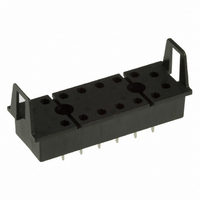
P7S-14P
Description
SOCKET PC MNT FOR G7S RELAY
Manufacturer
Omron
Series
G7Sr
Type
Socketr
Specifications of P7S-14P
Mounting Type
Through Hole
Number Of Positions
14
Termination Style
PC Pin
Current Rating
6A
Terminal Type
Through Hole
No. Of Pins
14
Svhc
No SVHC (15-Dec-2010)
Accessory Type
Socket
External Depth
47mm
External Length / Height
80.5mm
External
RoHS Compliant
Associated Relay Series
G7S
Mounting Style
Through Hole
Width
23 mm
Socket Mounting
Through Hole
Socket Terminals
Quick Connect
Rohs Compliant
Yes
Lead Free Status / RoHS Status
Lead free / RoHS Compliant
For Use With/related Products
G7S Series
For Use With
Z2362 - RELAY SAFETY 6A 24VDC PLUG-INZ2363 - RELAY SAFETY 6A 24VDC PLUG-IN
Lead Free Status / Rohs Status
Lead free / RoHS Compliant
Other names
P7S14P
Z2418
Z2418
Available stocks
Company
Part Number
Manufacturer
Quantity
Price
Company:

Part Number:
P7S-14P
Manufacturer:
Omron Electronics Inc-EMC Div
Quantity:
135


C-B-4 Applied Voltage Waveform for Input Voltage
As a rule, power supply waveforms are based on the rectangular
(square) waveforms, and do not operate in such a way that the
voltage applied to the coil slowly rises and falls. Also, do not use
them to detect voltage or current limit values (i.e., using them for
turning ON or OFF at the moment a voltage or current limit is
reached).
This kind of circuit causes faulty sequence operations. For example,
the simultaneous operability of contacts may not be dependable (for
multi-pole Relays, time variations must occur in contact operations),
and the must-operate voltage varies with each operation. In addition,
the operation and release times are lengthened, causing durability to
drop and contact welding. Be sure to use an instantaneous ON/OFF.
C-B-5 Preventing Surges when the Coil Is Turned OFF
Counter electromotive force generated from a coil when the coil is
turned OFF causes damage to semiconductor elements and faulty
operation.
As a countermeasure, install surge absorbing circuits at both ends of
the coil. When surge absorbing circuits have been installed, the
Relay release time will be lengthened, so be sure to check operation
using the actual circuits.
External surges must be taken into account for the repetitive peak
reverse voltage and the DC reverse voltage, and a diode with
sufficient capacity used. Also, ensure that the diode has an average
rectified current that is greater than the coil current.
Do not use under conditions in which a surge is included in the power
supply, such as when an inductive load is connected in parallel to the
coil. Doing so will cause damage to the installed (or built-in) coil
surge absorbing diode.
C-B-6 Leakage Current to Relay Coils
Do not allow leakage current to flow to Relay coils. Construct a
corrective circuit as shown in examples 1 and 2 below.
Example: Circuit with Leakage Current Occurring
Corrective Example 1
Corrective Example 2:
When an Output Value Is Required in the Same Phase as the
Input Value
C-B-7 Using with Infrequent Switching
For operations using a microload and infrequent switching,
periodically perform continuity tests on the contacts. When switching
is not executed for contacts for long periods of time, it causes contact
instability due to factors such as the formation of film on contact
surfaces. The frequency with which the inspections are needed will
depend on factors such as the operating environment and the type of
load.
http://www.ia.omron.com/
I
O
TE
Correct
Incorrect
Correct
C-B-8 Configuring Sequence Circuits
When configuring a sequence circuit, care must be taken to ensure
that abnormal operation does not occur due to faults such as sneak
current.
The following diagram shows an example of sneak current. After
contacts A, B, and C are closed causing Relays X
operate, and then contacts B and C are opened, a series circuit is
created from A to X
not release.
The following diagram shows an example of a circuit that corrects the
above problem. Also, in a DC circuit, the sneak current can be
prevented by means of a diode.
C-B-9 Connecting Relay Grounds
Do not connect a ground when using a Relay at high temperatures or
high humidity. Depending on the grounding method, electrolytic
corrosion may occur, causing the wire to the coil to sever. If the Relay
must be grounded, use the method shown in the following diagrams.
(1) Ground the positive side of the power supply. (Fig. 1 and Fig. 2)
(2) If grounding the positive side of the power supply is not possible
(3) Do not ground the negative side and connect a switch to the
C-B-10 Individual Specifications for Must-operate/
If it is necessary to know the individual specifications of
characteristics, such as must-operate voltages, must-release
voltages, operate times, and release times, please contact your
OMRON representative.
and the negative side must be grounded, connect a switch at the
positive side so that the coil is connected to the negative side.
(Fig. 3)
negative side. This will cause electrolytic corrosion to occur. (Fig.
4)
(c)Copyright OMRON Corporation 2007 All Rights Reserved.
Fig. 1
Fig. 3
release Voltages and Operate/Release Times
1
to X
C
A
A
C
X
X
1
Correct
Correct
1
2
to X
B
B
X
X
3
2
2
. This causes the Relay to hum or to
D
X
X
3
3
Difference in electric potential
Incorrect
Correct
Fig. 2
Fig. 4
1
, X
2
, and X
Incorrect
Correct
3
to
C-8
Related parts for P7S-14P
Image
Part Number
Description
Manufacturer
Datasheet
Request
R

Part Number:
Description:
Relay Sockets & Hardware G7 RELAY TRACK MT SOCKET
Manufacturer:
Omron
Datasheet:

Part Number:
Description:
Contact OSTI
Manufacturer:
Omron
Datasheet:

Part Number:
Description:
Relay Sockets & Hardware G7 relay PCB mounting
Manufacturer:
Omron
Part Number:
Description:
Relay Sockets & Hardware SOCKET
Manufacturer:
Omron
Datasheet:

Part Number:
Description:
G6S-2GLow Signal Relay
Manufacturer:
Omron Corporation
Datasheet:
Part Number:
Description:
Compact, Low-cost, SSR Switching 5 to 20 A
Manufacturer:
Omron Corporation
Datasheet:
Part Number:
Description:
Manufacturer:
Omron Corporation
Datasheet:
Part Number:
Description:
Manufacturer:
Omron Corporation
Datasheet:
Part Number:
Description:
Manufacturer:
Omron Corporation
Datasheet:
Part Number:
Description:
Manufacturer:
Omron Corporation
Datasheet: