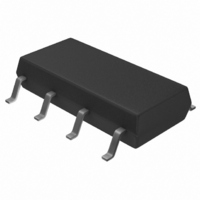
TLP4206G(F) Toshiba, TLP4206G(F) Datasheet

TLP4206G(F)
Specifications of TLP4206G(F)
Related parts for TLP4206G(F)
TLP4206G(F) Summary of contents
Page 1
... PBX Telecommunication Modem・FAX Cards, Modems In PC Measurement Instrumentation The TOSHIBA TLP4206G consists of an aluminum gallium arsenide infrared emitting diode optically coupled to a photo-MOSFET in a SOP, which is suitable for surface mount assembly. The TLP4206GA is a 2-Form-A switch, which is suitable for replacement of mechanical relays in many applications. ...
Page 2
... Please design the appropriate reliability upon reviewing the Toshiba Semiconductor Reliability Handbook (“Handling Precautions”/“Derating Concept and Methods”) and individual reliability data (i.e. reliability test report and estimated failure rate, etc). ...
Page 3
Coupled Electrical Characteristics Characteristics Trigger LED current Return LED current On-state resistance Isolation Characteristics Characteristics Capacitance input to output Isolation resistance Isolation voltage Switching Characteristics Characteristics Turn-on time Turn-off time Note 2: Switching time test circuit ...
Page 4
I – 100 − Ambient temperature Ta (°C) I – 100 Ta = 25° 0.5 0.3 0.1 0.6 0.8 ...
Page 5
I ON OFF F 2000 Ta = 25° 200 Ω 1000 t OFF 500 300 t ON 100 Input current I ...
Page 6
... Product shall not be used for or incorporated into any products or systems whose manufacture, use, or sale is prohibited under any applicable laws or regulations. • The information contained herein is presented only as guidance for Product use. No responsibility is assumed by TOSHIBA for any infringement of patents or any other intellectual property rights of third parties that may result from the use of Product. No license to any intellectual property right is granted by this document, whether express or implied, by estoppel or otherwise. • ...


