H5CX-A-N AC100-240 Omron, H5CX-A-N AC100-240 Datasheet - Page 42
H5CX-A-N AC100-240
Manufacturer Part Number
H5CX-A-N AC100-240
Description
RELAY TIMER DGTL SPDT 100/240VAC
Manufacturer
Omron
Series
H5CXr
Specifications of H5CX-A-N AC100-240
Mounting Type
Panel Mount
Relay Type
Integrated
Function
Programmable (Multi-Function)
Circuit
SPDT (1 Form C)
Delay Time
0.001 Sec ~ 9999 Hrs
Output Type
Mechanical Relay
Contact Rating @ Voltage
5A @ 250VAC
Voltage - Supply
100 ~ 240VAC
Termination Style
Screw Terminal
Timing Adjustment Method
DIP Switches
Timing Initiate Method
Input Voltage, Trigger Signal
Timing Range
0.001 s to 9999 Hrs
Supply Voltage
100 V to 240 V
Current Rating (max)
100 mA
Display Type
6 Digit LCD
Product
Digital Timer
Time Range
0.001s-9999hrs
Power Consumption
6.2VA
Reset Time
20ms
Character Size
11.5mm
Time Range Min
0.001s
Supply Voltage Min
100VAC
Connector Type
Screw Terminal
No. Of Digits / Alpha
4
Rohs Compliant
Yes
Lead Free Status / RoHS Status
Lead free / RoHS Compliant
For Use With
PNP/NPN
Lead Free Status / RoHS Status
Lead free / RoHS Compliant, Lead free / RoHS Compliant
Other names
H5CXANAC100240
Z2997
Z2997


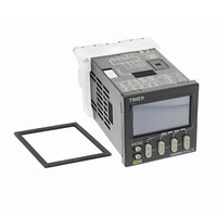
Nomenclature
■ Unit Label
The unit label is included with the Unit. Affix the unit label in the posi-
tion shown in the following diagram to match the time range to be
used.
Key Protection Indicator (orange)
Lit when the Key-protect Switch is
ON.
is ON.
Control Output Indicator (orange)
Forecast value setting:
Absolute value setting:
Reset Indicator (orange)
Lit when the reset input or Reset Key
Present Value (red)
Character height: 9 mm
If the time range is 0.0 min or 0.0 h,
the decimal point flashes to indicate
timing operation.
Set Value 1, 2 Display (green)
Set Value (green)
Character height: 6 mm
Forecast output ON: 1 is lit
Control output ON: 2 is lit
Control output 1 ON: 1 is lit
Control output 2 ON: 2 is lit
Indicator
Align the right edge of the label with the
right edge of the display window.
Unit label
Sixth digit
Front View
First digit
(Default setting)
When the Key-protect Switch is ON, key
operations are prohibited according to the
settings for DIP switch pins 6 to 8, thus
preventing setting errors. The Key-protect
Switch can be turned ON and OFF while
the power is ON. The Key Protection
Indicator is lit orange when the
Key-protect Switch is ON.
OFF
ON
(Default setting) OFF
Mode Key
(Changes setting items)
Reset Key
(Resets present value and output)
Up Keys 1 to 6
Key-protect Switch
DIP Switch
Refer to DIP Switch Settings on
page 45 for details on setting the
DIP switch.
1
Switches
Operation Key
2
3
4
5
ON
6
7
H5CX-B
8
42
Related parts for H5CX-A-N AC100-240
Image
Part Number
Description
Manufacturer
Datasheet
Request
R

Part Number:
Description:
Digital Timer
Manufacturer:
Omron Corporation
Datasheet:
Part Number:
Description:
Relay; E-Mech; Timing; Multi-Function; Cur-Rtg 5A; Ctrl-V 100-240AC; Socket Mnt; 8 Pin
Manufacturer:
Omron Automation
Datasheet:
Part Number:
Description:
Relay; E-Mech; Timing; Multi-Function; Cur-Rtg 5A; Ctrl-V 100-240AC; Socket Mnt; 11 Pin
Manufacturer:
Omron Automation
Datasheet:
Part Number:
Description:
Relay; E-Mech; Timing; Multi-Function; Cur-Rtg 5A; Ctrl-V 24/12-24AC/DC; Screw; 11 Pin
Manufacturer:
Omron Automation
Datasheet:
Part Number:
Description:
Relay; E-Mech; Timing; Multi-Function; Cur-Rtg 5A; Ctrl-V 24/12-24AC/DC; Socket Mnt
Manufacturer:
Omron Automation
Datasheet:
Part Number:
Description:
G6S-2GLow Signal Relay
Manufacturer:
Omron Corporation
Datasheet:
Part Number:
Description:
Compact, Low-cost, SSR Switching 5 to 20 A
Manufacturer:
Omron Corporation
Datasheet:
Part Number:
Description:
Manufacturer:
Omron Corporation
Datasheet:
Part Number:
Description:
Manufacturer:
Omron Corporation
Datasheet:
Part Number:
Description:
Manufacturer:
Omron Corporation
Datasheet:
Part Number:
Description:
Manufacturer:
Omron Corporation
Datasheet: