H5CX-BWSD Omron, H5CX-BWSD Datasheet - Page 18
H5CX-BWSD
Manufacturer Part Number
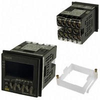
H5CX-BWSD
Description
TIMER DGTL DUAL 99KHRS 12-24VDC
Manufacturer
Omron
Series
H5CXr
Datasheet
1.Y92A-48F1.pdf
(51 pages)
Specifications of H5CX-BWSD
Relay Type
Integrated
Function
Programmable (Multi-Function)
Delay Time
0.01 Sec ~ 99K Hrs
Output Type
Transistor
Voltage - Supply
12 ~ 24VDC
Mounting Type
Panel Mount
Termination Style
Screw Terminal
Timing Adjustment Method
DIP Switches
Timing Initiate Method
Input Voltage, Trigger Signal
Lead Free Status / RoHS Status
Lead free / RoHS Compliant
Circuit
-
Contact Rating @ Voltage
-
Lead Free Status / Rohs Status
Lead free / RoHS Compliant
Other names
H5CXBWSD
Z2408
Z2408
Available stocks
Company
Part Number
Manufacturer
Quantity
Price
Company:

Part Number:
H5CX-BWSD-N
Manufacturer:
OMRON
Quantity:
1 000


■ Operating Procedures (Timer Function)
Settings for Basic Functions
Note: All the pins are factory-set to OFF.
Note 1. Be sure to set pin 1 of the DIP switch to ON. If it is set to OFF, the DIP switch settings will not be enabled.
1
2
3
4
5
6
7
8
Settings for basic functions can be performed with just the DIP switch.
Easy Confirmation of Switch Settings Using Indicators
The ON/OFF status of the DIP switch pins can be
confirmed using the front display. For details, refer to page 31.
After making DIP switch settings for basic functions, detailed settings (see note) can be added using the operation keys.
For details, refer to page 19.
Note: Output time, NPN/PNP input mode, display color, key protect level.
Detailed Settings
2. Changes to DIP switch settings are enabled when the power is turned ON. (Perform DIP switch settings while the power is OFF.)
3. There is no DIP switch on the H5CX-L8@. For details on the setting methods, refer to page 19.
4. When using time ranges or output modes that cannot be set with the DIP switch, all of the settings have to be made using the operation
keys. For details on the setting methods, refer to page 19.
DIP switch set-
tings enable/
disable
Time range
Output mode
Timer mode
Input signal
width
Item
Disabled
Refer to the table on the right.
Refer to the table on the right.
Elapsed time
(UP)
20 ms
OFF
OFF
ON
Enabled
Remaining time
(DOWN)
1 ms
1
ON
Be sure to set pin 1 to ON when using the DIP switch.
2
3
4
5
6
7
8
ON
OFF
ON
OFF
ON
OFF
ON
OFF
OFF
ON
OFF
ON
Pin 2
Pin 5
ON
OFF
OFF
ON
ON
OFF
OFF
ON
Pin 3
OFF
OFF
ON
ON
Pin 6
ON
OFF
OFF
OFF
OFF
ON
ON
ON
Pin 4
(I): power reset operation)
A-2 mode: (power ON de-
lay (I): power reset opera-
tion)
E mode (interval: power
reset operation)
F mode (accumulative:
power hold operation)
A mode (signal ON delay
0.001 s to 9.999 s
0.01 s to 99.99 s
0.1 s to 999.9 s
1 s to 9999 s
0 min 01 s to 99 min
59 s
0.1 min to
999.9 min
0 h 01 min to
99 h 59 min
0.1 h to 999.9 h
Output mode
Time range
H5CX-A/-L
18
Related parts for H5CX-BWSD
Image
Part Number
Description
Manufacturer
Datasheet
Request
R

Part Number:
Description:
RELAY TIMER DGTL SPDT 100/240VAC
Manufacturer:
Omron
Datasheet:

Part Number:
Description:
RELAY TIMER DGTL SPDT 12-24VDC
Manufacturer:
Omron
Datasheet:

Part Number:
Description:
RELAY TIMER DGTL SPDT 12-24VDC
Manufacturer:
Omron
Datasheet:
Part Number:
Description:
RELAY TIMER DGTL TRANS 12-24VDC
Manufacturer:
Omron
Datasheet:

Part Number:
Description:
Relay; E-Mech; Timing; Multi-Function; Cur-Rtg 5A; Ctrl-V 100-240AC; REPL:H5CX-AAC1002
Manufacturer:
Omron Automation
Datasheet:

Part Number:
Description:
RELAY TIMER DGTL SPDT 100/240VAC
Manufacturer:
Omron
Datasheet:

Part Number:
Description:
RELAY TIMER DGTL TRANS 12-24VDC
Manufacturer:
Omron
Datasheet:
Part Number:
Description:
RELAY TIMER DGTL TRANS 100-240V
Manufacturer:
Omron
Datasheet:
Part Number:
Description:
TIMER DGTL PRESET SPDT 11P
Manufacturer:
Omron
Datasheet:

Part Number:
Description:
Scrw Term,Trans OUT,Multi-Fnct
Manufacturer:
Omron
Datasheet:

Part Number:
Description:
8-PIN, RLY OUT, Limit, Instant DC12-24/AC24
Manufacturer:
Omron
Datasheet:
Part Number:
Description:
Relay; E-Mech; Timing; Multi-Function; Cur-Rtg 5A; Ctrl-V 100-240AC; Socket Mnt; 11 Pin
Manufacturer:
Omron Automation
Datasheet:
Part Number:
Description:
Relay; E-Mech; Timing; Multi-Function; Cur-Rtg 5A; Ctrl-V 24/12-24AC/DC; Screw; 11 Pin
Manufacturer:
Omron Automation
Datasheet:
Part Number:
Description:
Relay; E-Mech; Timing; Multi-Function; Cur-Rtg 5A; Ctrl-V 24/12-24AC/DC; Socket Mnt
Manufacturer:
Omron Automation
Datasheet:
Part Number:
Description:
Relay; E-Mech; Timing; Multi-Function; Cur-Rtg 5A; Ctrl-V 24/12-24AC/DC; Socket Mnt
Manufacturer:
Omron Automation
Datasheet: