I30 Fluke Electronics, I30 Datasheet
I30
Specifications of I30
614-1070
Available stocks


I30 Summary of contents
Page 1
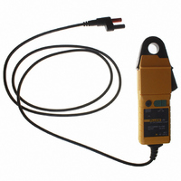
... Introduction The i30s AC/DC Current Clamp has been designed for use with oscilloscopes and DMMs for accurate, non-intrusive measurement of both AC, DC, and complex waveform currents. The i30 AC/DC Current Clamp has been designed for use with DMMs only. Using advanced Hall Effect technology the i30s can accurately measure currents with a resolution from over the frequency range 100 kHz ...
Page 2
... A Caution identifies conditions and actions that may damage the calibrator or the test instruments. The i30s and i30 may only be used and handled by qualified personnel. To avoid personal injury, follow these precautions: To avoid electric shock, use caution during installation and use of this product ...
Page 3
... Current range Measuring range Overload capacity Output sensitivity Accuracy (at 25 °C) Resolution Typical output noise level Load impedance Conductor position sensitivity Frequency range i30s i30 following Response time Temperature coefficient Operating humidity: Altitude: Power supply Working voltage (see Safety Standards) Battery life ...
Page 4
... General Characteristics Maximum conductor size Output cable and connections: i30s i30 Output zero Operating temperature range Storage temperature range (with battery removed) Weight 19 mm diameter 2 m cable terminated with a BNC connector (50 Ohms) supplied with safety adaptor 1.5 m cable terminated with a dual ...
Page 5
... Frequency in Hz 1000 i30s Frequency in Hz 100 1000 i30 Typical Frequency Response Frequency in Hz 1000 i30s Frequency in Hz 1000 i30 Typical Frequency Response 100000 10000 100000 100000 20000 100000 ehr01.eps ehr02.eps ...
Page 6
... BS EN 61010-2-032: 2002 BS EN 61010-031: 2002 CSA C22.2 No. 1010.1 , Category III, Pollution degree 2 300 V RMS Use of the probe on uninsulated conductors is limited to 300 V ACRMS or DC and frequencies below 1 kHz. EMC Standards BS EN 61326: 1998 +A1, A2, and A3 i30s i30 Typical Accuracy Curve ehr03.eps ...
Page 7
... Operating Instructions Figure 1. i30s & i30 AC/DC Current Clamps To avoid injury, when using the probe ensure that your fingers are behind the protective barrier as shown in Figure 1. Do not use the probe if any part of the probe, including the lead and connector(s), appear to be damaged malfunction of the instrument is suspected ...
Page 8
Current Measurement 1. Switch on the probe using the On – Off switch and check that the LED is lit. 2. Connect the output lead to an oscilloscope, multimeter, or other measuring equipment necessary adjust the probe output ...
Page 9
LIMITED WARRANTY AND LIMITATION OF LIABILITY This Fluke product will be free from defects in material and workmanship for one year from the date of purchase. This warranty does not cover fuses, disposable batteries, or damage from accident, neglect, misuse, ...
Page 10
...