I30 Fluke Electronics, I30 Datasheet - Page 8
I30
Manufacturer Part Number
I30
Description
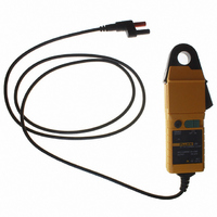
CLAMP CURRENT AC/DC 30A
Manufacturer
Fluke Electronics
Type
AC/DC Clamp, Hall Effectr
Datasheet
1.I30.pdf
(10 pages)
Specifications of I30
Style
Pincer
Ac Current Range
30mA ~ 20A rms
Bandwidth
20kHz
Cable Length
59.055" (1500.00mm)
Dc Current Range
5mA ~ 30A
Max Conductor Size
0.748" (19.00mm)
Termination
Banana Plug, Double, Sheathed
Ratings
CAT III 300V
Lead Free Status / RoHS Status
Not applicable / Not applicable
Other names
2584920
614-1070
614-1070
Available stocks
Company
Part Number
Manufacturer
Quantity
Price

Part Number:
I3002L-TP
Manufacturer:
INTERPION
Quantity:
20 000
Part Number:
I3010-13.000-9
Manufacturer:
ITTI
Quantity:
20 000


Current Measurement
Battery Replacement
The red LED will flash when the minimum operating voltage is
approached. Refer to Fig.1. Use the following procedure:
1.
2.
3.
4.
5.
To avoid personal injury, always ensure the probe is
removed from any live electric circuit, and leads are
disconnected before removing the battery cover.
Never operate the probe without the battery cover
fitted.
1.
2.
Replacement with other than the specified type of
battery will invalidate the warranty.
Fit only the type 9 V PP3 Alkaline (MN 1604).
Switch on the probe using the On – Off switch and
check that the LED is lit.
Connect the output lead to an oscilloscope, multimeter,
or other measuring equipment.
If necessary adjust the probe output voltage to zero as
described in section Zero Adjustment.
Clamp the jaw of the probe around the conductor
ensuring a good contact between the closing faces of
the jaws.
Observe and take measurements as required. Positive
output indicates that the current flow is in the direction
shown by the arrow on the probe.
Unclamp the probe from the conductor, turn it off using
the On – Off switch and disconnect the output leads,
from external equipment.
Loosen the captive screw that secures the battery
cover. Lift the cover through 30° and pull it clear of the
probe body as shown in Fig 1. The battery is then
accessible. Replace the battery and re-fit the battery
cover and fasten the screw.
W Warning
Note