90546-1 Tyco Electronics, 90546-1 Datasheet - Page 2
90546-1
Manufacturer Part Number
90546-1
Description
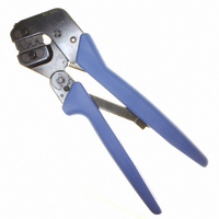
ASSY PRO-CRIMPER UNIV M-N-L
Manufacturer
Tyco Electronics
Series
Pro-Crimper™ III, Universal MATE-N-LOK®r
Type
Hand Toolr
Specifications of 90546-1
Tool Type
Hand Crimper
Features
Side Entry, Ratchet
Rohs Compliant
NA
Product
Crimping, Stripping & Cutting Tools & Drills
Description/function
Pro-Crimper III
Fits Cable/wire
20-14 AWG
Lead Free Status / RoHS Status
Not applicable / Not applicable
For Use With/related Products
Rectangular Contacts, 14-20 AWG
For Use With
926894-3 - CONN MAT-N-LOK 20-14AWG926893-6 - CONN MAT-N-LOK 20-14AWG926894-1 - CONN PIN 14-20AWG TIN CRIMP926893-1 - CONN SOCKET 14-20AWG TIN CRIMP926898-3 - CONN SPLIT PIN 14-20AWG TIN CRMP926898-1 - CONN SPLIT PIN 20-14AWG M-N-LOK926893-3 - CONN SOCKET 20-14AWG MATE-N-LOKA33357 - CONN SOCKET 14-20AWG GOLD CRIMPA31714 - CONN PIN 14-20AWG GOLD CRIMPA31706 - CONN PIN 14-20AWG GOLD CRIMPA25443 - CONN PIN GRND 14-20AWG AU CRIMPA25730 - CONN PIN 14-20AWG GOLD CRIMPA25694 - CONN PIN 14-20AWG GOLD CRIMPA25409 - CONN SOCKET 14-20AWG GOLD CRIMPA25372 - CONN SOCKET 14-20AWG GOLD CRIMPA25375 - CONN SOCKET 14-20AWG TIN CRIMPA25369 - CONN SOCKET 14-20AWG GOLD CRIMPA25343 - CONN PIN 14-20AWG TIN CRIMPA25346 - CONN PIN 14-20AWG GOLD CRIMPA25339 - CONN PIN GROUND 14-20AWG CRIMPA25336 - CONN PIN 14-20AWG GOLD CRIMPA25381 - CONN SOCKET 14-18AWG TIN CRIMPA25380 - CONN PIN 14-18AWG TIN CRIMPA25188 - CONN PIN 14-20AWG TIN CRIMPA25338 - CONN PIN 14-20AWG TIN CRIMPA25341 - CONN PIN 14-20AWG GOLD CRIMPA25344 - CONN SOCKET 14-20AWG TIN CRIMPA25347 - CONN SOCKET 14-20AWG GOLD CRIMPA25342 - CONN SOCKET 14-20AWG GOLD CRIMPA14302 - CONN SOCKET 14-20AWG TIN CRIMPA14301 - CONN PIN 14-20AWG GOLD CRIMPA14300 - CONN PIN 14-20AWG TIN CRIMPA14265 - CONN SOCKET 14-20AWG GOLD CRIMPA14264 - CONN SOCKET 14-20AWG TIN CRIMPA14257 - CONN PIN 14-20AWG GOLD CRIMPA14256 - CONN PIN 14-20AWG TIN CRIMPA1443 - CONN SOCKET 14-20AWG GOLD CRIMPA1442 - CONN PIN 14-20AWG GOLD CRIMPA1441 - CONN SOCKET 14-20AWG TIN CRIMPA1440 - CONN PIN 14-20AWG TIN CRIMP
Lead Free Status / Rohs Status
Lead free / RoHS Compliant
Other names
90546-1
A25160
A25160


Attached to the outside of the frame is a locator
assembly, which contains a locator, a spring retainer,
and a contact support.
Die retaining pins and die retaining screws are used
to position and secure the dies in the tool frame. A
nut is used on the upper die retaining screw to hold
the locator assembly in place.
3. INSTALLATION AND REMOVAL OF DIE SET
AND LOCATOR ASSEMBLY
2 of 6
1. Open the tool handles and remove the two die
retaining screws from the tool jaws.
2. Place the wire anvil and insulation anvil so that
their chamfered sides and their marked surfaces
face outward, when mounted in the moving jaw of
the tool frame.
3. Insert the two die retaining pins.
4. Insert the short die retaining screw through the
jaw and through both anvil dies, and tighten the
screw just enough to hold the dies in place. Do not
tighten the screw completely at this time.
5. Place the wire crimper and insulation crimper so
that their chamfered sides and their marked
surfaces face outward, when mounted in the
stationary jaw of the tool frame.
6. Insert the two die retaining pins.
7. Insert the long die retaining screw through the
jaw and through both crimper dies, and tighten the
Wire Crimper
Chamfer
Offset
Wire Anvil
Nut
Locator
Insulation
Anvil
(Figure 2)
Insulation
Crimper
Chamfer
Locator
Assembly
Figure 2
4. CONTACT SUPPORT ADJUSTMENT
NOTE
screw just enough to hold the dies in place. Do not
tighten the screw completely at this time.
8. Carefully close the tool handles, making sure
that the anvils and crimpers align properly.
Continue closing the tool handles until the ratchet
in the tool frame has engaged sufficiently to hold
the anvils and crimpers in place, then tighten both
die retaining screws.
9. Place the locator assembly over the end of the
long screw, and position the locator assembly
against the side of the tool jaw.
10. Place the nut onto the end of the long screw
and tighten the nut enough to hold the locator
assembly in place, while still allowing the locator to
slide up and down.
11. To disassemble, close the tool handles until the
ratchet releases, remove the nut, the locator
assembly, the two die retaining screws, and the
four die retaining pins, and slide the anvils and
crimpers out of the tool jaws.
1. Make a sample crimp and determine if the
contact is straight, bending upward, or bending
downward.
i
The contact support is preset prior to shipment,
but minor adjustment may be necessary.
Die Retaining
Screws
Tool Frame
Die Retaining
Pins
(Figure 3)
408- 9883
Rev D