90546-1 Tyco Electronics, 90546-1 Datasheet - Page 4
90546-1
Manufacturer Part Number
90546-1
Description
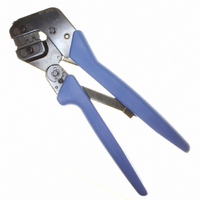
ASSY PRO-CRIMPER UNIV M-N-L
Manufacturer
Tyco Electronics
Series
Pro-Crimper™ III, Universal MATE-N-LOK®r
Type
Hand Toolr
Specifications of 90546-1
Tool Type
Hand Crimper
Features
Side Entry, Ratchet
Rohs Compliant
NA
Product
Crimping, Stripping & Cutting Tools & Drills
Description/function
Pro-Crimper III
Fits Cable/wire
20-14 AWG
Lead Free Status / RoHS Status
Not applicable / Not applicable
For Use With/related Products
Rectangular Contacts, 14-20 AWG
For Use With
926894-3 - CONN MAT-N-LOK 20-14AWG926893-6 - CONN MAT-N-LOK 20-14AWG926894-1 - CONN PIN 14-20AWG TIN CRIMP926893-1 - CONN SOCKET 14-20AWG TIN CRIMP926898-3 - CONN SPLIT PIN 14-20AWG TIN CRMP926898-1 - CONN SPLIT PIN 20-14AWG M-N-LOK926893-3 - CONN SOCKET 20-14AWG MATE-N-LOKA33357 - CONN SOCKET 14-20AWG GOLD CRIMPA31714 - CONN PIN 14-20AWG GOLD CRIMPA31706 - CONN PIN 14-20AWG GOLD CRIMPA25443 - CONN PIN GRND 14-20AWG AU CRIMPA25730 - CONN PIN 14-20AWG GOLD CRIMPA25694 - CONN PIN 14-20AWG GOLD CRIMPA25409 - CONN SOCKET 14-20AWG GOLD CRIMPA25372 - CONN SOCKET 14-20AWG GOLD CRIMPA25375 - CONN SOCKET 14-20AWG TIN CRIMPA25369 - CONN SOCKET 14-20AWG GOLD CRIMPA25343 - CONN PIN 14-20AWG TIN CRIMPA25346 - CONN PIN 14-20AWG GOLD CRIMPA25339 - CONN PIN GROUND 14-20AWG CRIMPA25336 - CONN PIN 14-20AWG GOLD CRIMPA25381 - CONN SOCKET 14-18AWG TIN CRIMPA25380 - CONN PIN 14-18AWG TIN CRIMPA25188 - CONN PIN 14-20AWG TIN CRIMPA25338 - CONN PIN 14-20AWG TIN CRIMPA25341 - CONN PIN 14-20AWG GOLD CRIMPA25344 - CONN SOCKET 14-20AWG TIN CRIMPA25347 - CONN SOCKET 14-20AWG GOLD CRIMPA25342 - CONN SOCKET 14-20AWG GOLD CRIMPA14302 - CONN SOCKET 14-20AWG TIN CRIMPA14301 - CONN PIN 14-20AWG GOLD CRIMPA14300 - CONN PIN 14-20AWG TIN CRIMPA14265 - CONN SOCKET 14-20AWG GOLD CRIMPA14264 - CONN SOCKET 14-20AWG TIN CRIMPA14257 - CONN PIN 14-20AWG GOLD CRIMPA14256 - CONN PIN 14-20AWG TIN CRIMPA1443 - CONN SOCKET 14-20AWG GOLD CRIMPA1442 - CONN PIN 14-20AWG GOLD CRIMPA1441 - CONN SOCKET 14-20AWG TIN CRIMPA1440 - CONN PIN 14-20AWG TIN CRIMP
Lead Free Status / Rohs Status
Lead free / RoHS Compliant
Other names
90546-1
A25160
A25160


6. CRIMP HEIGHT INSPECTION
Crimp height inspection is performed through the use
of a micrometer with a modified anvil, commonly
referred to as a crimp--height comparator. TE does
not manufacture or market crimp--height comparators.
Detailed information on obtaining and using
crimp--height comparators can be found in instruction
sheet 408--7424.
4 of 6
CAUTION
Position Point
on Center of
Wire Barrel
Opposite
Seam
Modified Anvil
AWG (Max)
Wire Size
Wire Size
4. Hold the contact in position and squeeze the
tool handles together until ratchet engages
sufficiently to hold the contact in position. Do NOT
deform insulation barrel or wire barrel.
5. Insert stripped wire into contact insulation and
wire barrels until it is butted against the wire stop,
as shown in Figure 3.
6. Holding the wire in place, squeeze tool handles
together until ratchet releases. Allow tool handles
to open and remove crimped contact.
NOTE
7. Check the contact’s crimp height as described in
Section 6, CRIMP HEIGHT INSPECTION. If
necessary, adjust the crimp height as described in
Section 7, RATCHET (Crimp Height)
ADJUSTMENT.
!
i
18
14
Make sure that both sides of the insulation barrel
are started evenly into the crimping section. Do
NOT attempt to crimp an improperly positioned
contact.
The crimped contact may stick in the crimping
area, but the contact can be easily removed by
pushing downward on the top of the locator (see
Figure 3).
(Wire Size Marking)
Crimp Section
Crimp Section
20--18
16--14
Figure 4
“A”
Crimp Height
Tolerance (+)
[.050.002]
[.063.002]
Dim A and
Dim A and
1.27.05
1.60.05
Proceed as follows:
7. RATCHET (Crimp Height) ADJUSTMENT
1. Refer to Figure 4 and select a wire (maximum
size) for each crimp section listed.
2. Refer to Section 5, CRIMPING PROCEDURE,
and crimp the contact(s) accordingly.
3. Using a crimp height comparator, measure the
wire barrel crimp height as shown in Figure 4. If the
crimp height conforms to that shown in the table,
the tool is considered dimensionally correct. If not,
the tool must be adjusted. Refer to Section 7,
RATCHET (Crimp Height) ADJUSTMENT.
1. Remove the lockscrew from the ratchet
adjustment wheel.
2. With a screwdriver, adjust the ratchet wheel
from the locator side of the tool.
3. Observe the ratchet adjustment wheel. If a
tighter crimp is required, rotate the adjustment
wheel COUNTERCLOCKWISE to a
higher--numbered setting. If a looser crimp is
required, rotate the adjustment wheel
CLOCKWISE to a lower--numbered setting.
4. Replace the lockscrew.
5. Make a sample crimp and measure the crimp
height. If the dimension is acceptable, replace and
secure the lockscrew. If the dimension is
unacceptable, continue to adjust the ratchet, and
again measure a sample crimp.
Ratchet
Adjustment
Wheel
Lockscrew
(Typ)
Screwdriver
Figure 5
(Figure 5)
408- 9883
Rev D