2-231652-8 Tyco Electronics, 2-231652-8 Datasheet - Page 2
2-231652-8
Manufacturer Part Number
2-231652-8
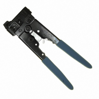
Description
TOOL CRIMP MOD 2,4,6POS WITH DIE
Manufacturer
Tyco Electronics
Specifications of 2-231652-8
Tool Type
Hand Crimper, Cutter, Stripper
Features
Top Entry, Ratchet
Crimp Tool
Hand Held Crimp Tool
Color
Blue
Product
Tools
For Use With
554603-2 - CONN MOD PLUG 6-6 ROUND554603-1 - CONN MOD PLUG 6-6 ROUND5-569032-2 - CONN MOD PLUG 6-6 ROUND SOLID5-554710-1 - CONN MOD PLUG 6-6 ROUND STRANDED5-557971-3 - CONN MOD PLUG 6-6 FLAT OVAL5-557970-2 - CONN MOD PLUG 6-6 FLAT OVAL5-569031-2 - CONN MOD PLUG 6-4 ROUND STRANDED5-557967-2 - CONN MOD PLUG 4-4 FLAT OVAL5-557965-3 - CONN MOD PLUG 6-4 FLAT OVAL5-556200-2 - CONN MOD PLUG 4-4 FLAT OVAL5-641334-1 - CONN MOD PLUG 4-4 FLAT OVAL5-569032-3 - CONN PLUG MOD 6POS ROUND SOLID5-569030-3 - CONN PLUG MOD 4POS ROUND SOLID5-569031-3 - CONN PLUG MOD 4POS STRANDED WIRE5-641337-2 - MOD PLUG ASSY/6POS/LINE 1000/BOX5-641337-4 - MOD PLUG ASSY/6 POS/LINE 25/BAG5-641337-1 - MOD PLUG ASSY, 6 POSN, LINE5-641335-7 - MOD PLUG ASSY/4POS/LINE 25/PKG5-641335-1 - MOD PLUG ASSY, 4 POSN, LINE5-641334-7 - MOD PLUG ASSY/4POS/HNDSET 1000PC5-641334-2 - MOD PLUG ASSY/4POS/HNDSET 1000PCA24921 - CONN MOD PLUG 6-2 FLAT OVAL AUA24922 - CONN MOD PLUG 6-4 FLAT OVAL AU5-556384-2 - MOD PLG ASSY/4POS/SLD WR 1000PC5-555042-4 - MOD PLG ASSY/6POS/24-26 AWG 25PC5-555042-2 - MOD PLUG ASSY/6 POS/24-26 AWG5-554710-4 - MOD PLG ASSY/6POS/ROUND CBL 25PC5-554710-2 - MOD PLG ASSY/6POS/ROUNDCABLEA9119 - CONN MOD PLUG 6-6 FLAT OVAL AUA9118 - CONN MOD PLUG 6-6 FLAT OVAL AUA9117 - CONN MOD PLUG 6-6 ROUND STRANDEDA9116 - CONN MOD PLUG 6-4 FLAT OVAL AU5-641335-2 - CONN PLUG MOD 6-4POS 50GOLDA9093 - CONN MOD PLUG 6-6 FLAT OVAL AUA9092 - CONN MOD PLUG 6-4 FLAT OVAL AUA9091 - CONN MOD PLUG 4-4 FLAT OVAL AU
Lead Free Status / RoHS Status
Not applicable / Not applicable
For Use With/related Products
Modular - RJ22 (4p4c), RJ11/12 ((6p6c)
Lead Free Status / Rohs Status
Lead free / RoHS Compliant
Other names
1-231652-2
1-231652-8
231652-2
A9901
1-231652-8
231652-2
A9901


3. CABLE PREPARATION
Refer to Figure 3, and select the appropriate cable and
die set for the modular plug being used. Then proceed
as follows:
3.1. Unshielded Flat Oval Cable
3.2. Shielded Flat Oval Cable and Round Cable
Prepare the cable according to Application
Specification 114-6016.
3.3. High Performance Cable
Prepare the cable according to Application
Specification 114-6053.
4. TERMINATION PROCEDURE
Before proceeding with the termination procedure,
check to make sure that the cable and modular plug
are compatible, and that cable polarity is correctly
maintained for the specific application.
Before proceeding with the termination procedure for
high performance modular plugs, refer to 114-6053 for
preparation techniques to ensure high performance
levels.
Refer to Figure 5, and proceed as follows:
Rev M
CAUTION
1. Insert cable squarely into CUT slot in tool cable
cutter. Squeeze handles until ratchet releases.
2. Insert trimmed cable into STRIP slot in tool flat
oval cable stripper until cable butts against die cable
stop.
3. Close handles to last ratchet stop, but DO NOT
release them. Pull cable straight out of tool. Then
release tool handles.
4. Check cable strip length as shown in Figure 4.
1. Hold modular plug as shown (locking latch facing
UP). Insert cable into modular plug until fully
bottome
2. Open tool handles. Insert modular plug assembly
fully into die cavity. When using a die set color
coded with green, orange, or blue, make sure that
the modular plug locking latch snaps into position.
NOTE
NOTE
i
i
!
The dies bottom before the ratchet releases. This
feature ensures maximum electrical and tensile
performance of the crimp. DO NOT re-adjust the
ratchet.
DO NOT squeeze handles together while pulling
cable out. Rather, with handles closed (but not
released) grip head of tool in one hand and cable in
the other; then pull cable straight out of tool.
DO NOT cut or remove insulation from individual
conductors. This may result in shorted or open
terminations within the terminated assembly.
(Figure 4)
CAUTION
When using a die set color coded with black, violet,
or white, make sure that the modular plug bottoms
in the die cavity but the locking latch does not snap
into position.
!
Failure to fully seat the modular plug assembly in
the die cavity will cause the indenter to mis-align
with the internal strain reliefs of the modular plug,
which may result in damage to the die set.
Figure 3
408-9767
2 of 7