2-231652-8 Tyco Electronics, 2-231652-8 Datasheet - Page 4
2-231652-8
Manufacturer Part Number
2-231652-8
Description
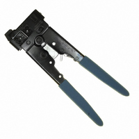
TOOL CRIMP MOD 2,4,6POS WITH DIE
Manufacturer
Tyco Electronics
Specifications of 2-231652-8
Tool Type
Hand Crimper, Cutter, Stripper
Features
Top Entry, Ratchet
Crimp Tool
Hand Held Crimp Tool
Color
Blue
Product
Tools
For Use With
554603-2 - CONN MOD PLUG 6-6 ROUND554603-1 - CONN MOD PLUG 6-6 ROUND5-569032-2 - CONN MOD PLUG 6-6 ROUND SOLID5-554710-1 - CONN MOD PLUG 6-6 ROUND STRANDED5-557971-3 - CONN MOD PLUG 6-6 FLAT OVAL5-557970-2 - CONN MOD PLUG 6-6 FLAT OVAL5-569031-2 - CONN MOD PLUG 6-4 ROUND STRANDED5-557967-2 - CONN MOD PLUG 4-4 FLAT OVAL5-557965-3 - CONN MOD PLUG 6-4 FLAT OVAL5-556200-2 - CONN MOD PLUG 4-4 FLAT OVAL5-641334-1 - CONN MOD PLUG 4-4 FLAT OVAL5-569032-3 - CONN PLUG MOD 6POS ROUND SOLID5-569030-3 - CONN PLUG MOD 4POS ROUND SOLID5-569031-3 - CONN PLUG MOD 4POS STRANDED WIRE5-641337-2 - MOD PLUG ASSY/6POS/LINE 1000/BOX5-641337-4 - MOD PLUG ASSY/6 POS/LINE 25/BAG5-641337-1 - MOD PLUG ASSY, 6 POSN, LINE5-641335-7 - MOD PLUG ASSY/4POS/LINE 25/PKG5-641335-1 - MOD PLUG ASSY, 4 POSN, LINE5-641334-7 - MOD PLUG ASSY/4POS/HNDSET 1000PC5-641334-2 - MOD PLUG ASSY/4POS/HNDSET 1000PCA24921 - CONN MOD PLUG 6-2 FLAT OVAL AUA24922 - CONN MOD PLUG 6-4 FLAT OVAL AU5-556384-2 - MOD PLG ASSY/4POS/SLD WR 1000PC5-555042-4 - MOD PLG ASSY/6POS/24-26 AWG 25PC5-555042-2 - MOD PLUG ASSY/6 POS/24-26 AWG5-554710-4 - MOD PLG ASSY/6POS/ROUND CBL 25PC5-554710-2 - MOD PLG ASSY/6POS/ROUNDCABLEA9119 - CONN MOD PLUG 6-6 FLAT OVAL AUA9118 - CONN MOD PLUG 6-6 FLAT OVAL AUA9117 - CONN MOD PLUG 6-6 ROUND STRANDEDA9116 - CONN MOD PLUG 6-4 FLAT OVAL AU5-641335-2 - CONN PLUG MOD 6-4POS 50GOLDA9093 - CONN MOD PLUG 6-6 FLAT OVAL AUA9092 - CONN MOD PLUG 6-4 FLAT OVAL AUA9091 - CONN MOD PLUG 4-4 FLAT OVAL AU
Lead Free Status / RoHS Status
Not applicable / Not applicable
For Use With/related Products
Modular - RJ22 (4p4c), RJ11/12 ((6p6c)
Lead Free Status / Rohs Status
Lead free / RoHS Compliant
Other names
1-231652-2
1-231652-8
231652-2
A9901
1-231652-8
231652-2
A9901


Rev M
6.02±0.13 [.237±.005
B
(See
Table)
Standard and Blue
CAUTION
MODULAR PLUG
(Small Conductor)
High Performance
3. Hold the modular plug in the fully seated position,
and squeeze tool handles until ratchet releases.
4. Depress the modular plug locking latch (if
applicable), and remove terminated modular plug
assembly from the tool.
5. Inspect the modular plug assembly for proper
crimp height using a dial indicator or digital indicator
with needle-point probes or Crimp Height Gage
904170-1 according to 408-4389. Figure 6 shows a
cross-section of a typical terminated modular plug,
proper crimp height dimension, and required
location of the conductors. A visual inspection
through the plastic housing of the modular plug
should reveal whether the conductors are within
acceptable range.
NOTE
NOTE
NOTE
i
i
i
!
TYPE
Cross Section of Crimped Modular Plug
Terminated Modular Plug Inspection
When crimping, make sure to hold the modular
plug in the fully seated position to prevent the
modular plug from pushing out during the
termination procedure.
For specific information concerning inspection
requirements, refer to 114-6016 for standard and
blue (small conductor) modular plugs and 114-6053
for high performance modular plugs.
Once a termination has been made, DO NOT re-
terminate the modular plug. Replace damaged
modular plugs with new ones.
A (See Table)
(Reference Zone)
[.000 - .025]
Terminal
0.00 - 0.64
0.00 - 0.25
[.000 .010]
Figure 6
CONDUCTOR LOCATION
A
Note: Not to Scale
End of Wire Circuits
Conductors Against
(Prefered)
B
Note: The gage cannot be used for 4-position
handset and 6-position offset modular plugs.
5. ADJUSTMENTS
5.1. .Installing, Replacing, or Changing Die Set
5.2. Adjusting Flat Oval Cable Stripper
If cable jacket is cut too shallow and does not strip
properly from the conductor bundle or if it is cut too
deeply and conductor insulation is also cut, adjust the
flat oval cable stripper on the tool according to the
following.
Modular Plug
(See NOTE)
1. Squeeze tool handles until ratchet releases.
2. Using a small flat blade screwdriver or cross-
recessed screwdriver, remove the die holding screw
(turn the screw counterclockwise).
3. Using the screwdriver, push the die set out of the
tool.
4. Insert the die set with the color dots facing
outward as shown in Figure 1.
5. Close the tool handles. Re-install the die holding
screw (turn the screw clockwise until tight).
1. Close tool handles until the dies bottom, but DO
NOT release the handles.
2. Loosen the two screws that hold the movable
blade assembly.
3. Insert Blade Set-Up Gage 231667-2 (available
separately and part of Blade Replacement Kit
231662-4) or a 1.02-mm [.040-in.] shim between the
stationary and movable blades. Slide the movable
blade against the gage or shim, and tighten the
screws.
NOTE
NOTE
i
i
Crimp Height Gage 904170-1 is available to be
used as a quick verification of acceptable crimp
height as shown in Figure 7. Refer to 408-4389 for
instructions on using the gage.
The die set must be in the tool when adjusting the
flat oval cable stripper.
Checking Crimp Height
Figure 7
Crimp Height Gage
(Figure 8)
408-9767
4 of 7