58063-2 Tyco Electronics, 58063-2 Datasheet - Page 2
58063-2
Manufacturer Part Number
58063-2
Description
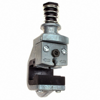
HEAD ASSEMBLY TOOL FOR D-SUB CON
Manufacturer
Tyco Electronics
Series
AMPLIMITE® HDE-20r
Type
Terminating Headr
Specifications of 58063-2
Connector Type
D-Sub Connector Contacts
Crimp Handle
A2031-ND, 58075-1-ND, 58338-1-ND, 931800-1-ND
Crimp Or Cable Size
20-30 AWG
Product
Tool Component
Lead Free Status / RoHS Status
Not applicable / Not applicable
For Use With
58075-1 - TOOL HANDLE PNEUMATIC W/O HEAD931800-1 - ELEC PWR UNIT W/O F/TRK OR HD58338-1 - PWR BENCH ASSEMBLY W/O HEADS
Lead Free Status / Rohs Status
Lead free / RoHS Compliant
Other names
A2032


4. ADJUSTMENTS
4.1. Wire Insertion Depth
If the wire is inserted too deep or not deep enough in
the contact after termination, adjust the wire insertion
depth as follows:
A. Pneumatic Power Units
Increase the air pressure by 10 psi [69 kPa]. Repeat
the termination and inspection procedure. Continue in
this manner until the proper wire insertion depth is
obtained or the air pressure is set to 70 psi [483 kPa].
If proper wire insertion depth is not obtained at 70 psi
[483 kPa], return the air pressure to 40 psi [276 kPa]
and follow Paragraph B.
2 of 4
DANGER
Slide Connector
Into Feed Channel
4. Repeat Steps 2 and 3 until all applicable
contacts are terminated.
5. Slide the connector out of the head in the
direction of the arrow.
6. Inspect each terminated contact according to
Figure 4. If any contact does not meet the
requirements, DO NOT use the connector. Refer to
Section 4 for adjustments.
NOTE
NOTE
i
i
Connector
For application requirements for the connectors,
refer to application specification 114- - 40002.
For assembly procedure, refer to 408- - 6621 for
all plastic connectors and 408- - 6645 for metal
shell connectors.
To avoid personal injury when using pneumatic
power units, ALWAYS disconnect the air supply
before making any adjustments.
For pneumatic power units, it might be necessary
to adjust either the air pressure or the adjuster
(inserter rod).
Terminating Connector
Wire
Figure 2
Wire
Slot
Power Unit
Tyco Electronics Corporation
(Ref)
B. Manual and Electric Power Units
4.2. Wire Guide
If the connector cannot be inserted into the head, the
connector is too loose in the head, or the connector
housing is damaged after termination, refer to Figure
1, and adjust the wire guide as follows:
5. INSPECTION AND MAINTENANCE
5.1. Inspection
Regular inspections should be performed by quality
control personnel with a record of quality control
inspections remaining with the personnel responsible
DANGER
1. Remove the head from the power unit according
to the instructions packaged with the power unit.
Make sure to observe any cautions and dangers.
2. Turn the adjuster (inserter rod) one--sixth of a
revolution clockwise if the wire is too deep in the
contact, and counterclockwise if the wire is not
deep enough in the contact. Refer to Figure 3. This
will decrease or increase the wire insertion depth
by approximately 0.20 mm [.008 in.].
3. Install the head onto the power unit according to
the instructions packaged with the power unit.
Make sure to observe any cautions and dangers.
1. For pneumatic power units, disconnect the air
supply. For electric power units, disconnect the
electrical power supply.
2. Loosen the two screws on the wire guide.
3. Slide the wire guide until the connector fits
properly in the head.
4. Finger--tighten the screws.
Turn COUNTERCLOCKWISE
To Increase
Wire Insertion Depth
Wire Insertion Depth Adjustment
To prevent personal injury when using electric
power units, ALWAYS disconnect the electrical
power supply before making any adjustments.
Figure 3
Turn CLOCKWISE
To Decrease
Wire Insertion Depth
Adjuster
(Inserter Rod)
Rev B