58442-1 Tyco Electronics, 58442-1 Datasheet - Page 3
58442-1
Manufacturer Part Number
58442-1
Description
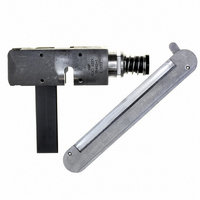
TOOL HEAD ASSEMBLY RCPT MTA 100
Manufacturer
Tyco Electronics
Series
MTA-100r
Type
Hand Toolr
Specifications of 58442-1
Crimp Application
Connectors
Product
Crimping, Stripping & Cutting Tools & Drills
Description/function
Crimp tool assembly for discrete wire MTA-100 receptacles
For Use With
MTA-100 Feed-Through Receptacles
Lead Free Status / RoHS Status
Not applicable / Not applicable
Lead Free Status / RoHS Status
na, Not applicable / Not applicable
Other names
58442-1
A9973
A9973


5. TERMINATION INSPECTION
Refer to Figure 3, and inspect each termination to
ensure the following:
Rev C
Feed-Through Head Assembly 58442-1
the direction of the arrow) until it stops, then
release the trigger or foot pedal (the receptacle
should advance so that the first contact aligns with
the wire inserter).
4. Check that the locating pawl is resting between
the index ribs of the receptacle. See Figure 2. If
not, push the receptacle out of the RIGHT side of
the head, and re–insert it.
NOTE
5. Insert an unstripped wire into the funnel area
between the contact and the wire inserter
in the desired location to be terminated.
6. Actuate the tool according to the
included with the tool. When the cycle is
completed, the wire inserter will retract, and the
feed slide will automatically advance the receptacle
to the next contact position.
NOTE
7. Repeat Steps 4 through 6 until all contacts have
been terminated.
8. Inspect each termination according to Section 5.
— the wire is terminated past the lead–in transition
and is about halfway in the contact slot
— the wire is from 1.78 to 2.16 mm [.070 to
.085 in.] beyond the front of the contact beam
— the wire is NOT bottomed in the contact slot
— the contact beams are NOT deformed (if
damage is apparent, replace the contacts in
accordance with the instructions packaged with the
receptacle)
— the wire is NOT nicked or cut in any area other
than the contact slot
— the wires extend beyond the strain–reliefs of the
receptacle
NOTE
i
i
i
After making the test crimp, the wire
sub-assembly retainer can be used (as shown in
Figure 2) to hold and locate the wires during
terminations. Pivot the retainer latch to open the
retainer.
The locating pawl will move up and down as the
receptacle is automatically advanced through the
head. However, if movement is obstructed, or if
desired, depress the locating pawl and push the
receptacle out of the RIGHT side of the head.
Refer to 114-1031 for detailed application
requirements.
instructions
until it is
Tyco Electronics Corporation
6. MAINTENANCE AND INSPECTION
The following procedures have been established to
ensure the quality and reliability of the head. The
head should be checked daily, and a more detailed
inspection should be performed by your quality control
group on a regular basis.
6.1. Daily Maintenance
Each operator should be aware of, and responsible
for, the following steps of maintenance.
Strain Relief
Inspection of Properly Terminated Wire
Wire Insertion Depth Adjustment
Contact Beam
Turn Counterclockwise to Increase
Wire Insertion Depth
Front of
Figure 3
Figure 4
Deformation
Turn Clockwise to Decrease
Wire Insertion Depth
Contact
Slot
Incorrect
Correct
Rod Inserter
Adjuster
Cut in Wire
Lead-In
Transition
Wire
408-9603
3 of 5