853400-8 Tyco Electronics, 853400-8 Datasheet - Page 4
853400-8
Manufacturer Part Number
853400-8
Description
DIE, 6 POS MOD PLUG IS9611
Manufacturer
Tyco Electronics
Type
Dier
Datasheets
1.1673606-1.pdf
(8 pages)
2.2-231652-0.pdf
(7 pages)
3.853400-1.pdf
(2 pages)
4.853400-1.pdf
(6 pages)
Specifications of 853400-8
Connector Type
Modular Connector, 6 pos
Crimp Handle
A9931-ND (2-231652-0)
Rohs Compliant
NA
Product
Punches & Dies
Lead Free Status / RoHS Status
Not applicable / Not applicable
Crimp Or Cable Size
-
Lead Free Status / Rohs Status
Lead free / RoHS Compliant
Other names
231651-2
313879-2
853400-2
A9905
313879-2
853400-2
A9905


4 of 6
Step 2
Step 1
Step 3
4. After releasing the terminated plug, inspect for
proper crimp height using a dial indicator or digital
indicator with needle--point probes, or Crimp Height
Gage 904170--1 according to 408--4389.
5. Figure 5 shows a cross--section of a typical
terminated plug—proper crimp height dimension
and required location of the conductors. A visual
inspection through the plastic housing of the plug
should reveal whether the conductors are within
acceptable range.
NOTE
i
Refer to 114- - 6016 for specific information
concerning inspection requirements.
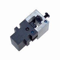
Die
Cavity
Terminating Modular Plug
Plug Locking
Tab
Figure 4
Cable Bottomed in Plug
Plug Oriented as
Shown on Side
of Tool Head
Locking
Tab (Ref)
Tyco Electronics Corporation
5. TOOL ADJUSTMENTS
5.1. Adjusting the Cable Stripper
If cable jacket is cut too shallow and does not strip
properly from the conductor bundle, or if it is cut too
deeply and conductor insulation is also cut, then refer
to Figure 6 and adjust the cable stripper on the hand
tool as follows:
5.2. Replacing Cable Stripper Blades
If the cable stripper blades are worn or damaged,
refer to Figure 7 and replace the fixed blade assembly
and movable blade assembly as follows:
CAUTION
NOTE
1. Close tool handles until the dies bottom, but DO
NOT release the handles.
2. Loosen the two screws that hold the movable
blade assembly.
3. Insert the blade set--up gage (part of the blade
replacement kit included with the tool) or a
1.02 mm [.040 in.] shim between the stationary
and movable blades. Slide the movable blade
against the gage (or shim) and tighten the screws.
NOTE
1. Remove the four screws holding both blades in
place. Remove fixed blade assembly and movable
blade assembly from tool.
2. Position new blades onto tool with beveled
edges facing inward.
i
!
i
6.02+0.13 [.237+.005]
Crimp Height
Crimped Modular Plug Inspection
The die set must be in the tool when adjusting
the flat cable stripper.
Do NOT cycle hand tool without a die in place.
Damage to the stripping blades may occur.
The recommended shim thickness does not
account for larger than normal conductor
insulation. Adjust the blade gap according to your
specific needs.
0.64 [.025] (Max)
Conductor Location
Figure 5
Cross- - Section of
Crimped Modular Plug
Rev D