90391-3 Tyco Electronics, 90391-3 Datasheet - Page 3
90391-3
Manufacturer Part Number
90391-3
Description
DIE SET ULTRA-FASTONS 16-14 AWG
Manufacturer
Tyco Electronics
Series
Pro-Crimper™ III, Faston™r
Type
Crimpersr
Specifications of 90391-3
Connector Type
Terminals and Splices
Crimp Handle
A28005-ND
Crimp Or Cable Size
14-16 AWG
Receptacles And Tabs ,tyco Electronics / Amp
ROHS COMPLIANT
Fits Cable/wire
16-14 AWG
Product
Tool Component
Lead Free Status / RoHS Status
Not applicable / Not applicable
For Use With
Platform Hand Tool Frame 58078-3
Lead Free Status / RoHS Status
Not applicable / Not applicable
Other names
90391-3
A28008
A28008


4. CRIMPING PROCEDURE
Rev
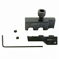
Die
Stop
Die Retaining
Screw
Setscrew
(Flush
on Both
Sides)
1. Refer to the table in Figure 2, select a wire of
the specified size and strip the wire to the
dimension provided. Do NOT nick or cut the wire
strands.
2. Select an applicable contact. See Figure 2.
3. Hold the tool so that the front of the tool is
facing you.
4. Make sure that the ratchet is released. Squeeze
the tool handles together and allow them to open
fully.
5. Rotate the blue plastic locator stop index to the
appropriate position.
6.Insert the terminal into the proper crimp section.
In–line terminals may be crimped in either in–line
section. Flag terminals must be crimped in the flag
crimp section. See Figure 4.
B
S When crimping a 110 series terminal, rotate the
S When crimping a 187 or 250 series terminal,
S For in–line terminals, the flat side of the
index until the number “110” appears in the
uppermost position.
rotate the index until the numbers “250–187”
appear in the uppermost position.
terminal must seat on the locator.
Figure 3
Locator
Crimping Die Assemblies 90390-3 and 90391-3
Upper Die
Lower Die
5. MAINTENANCE/INSPECTION
5.1. Daily Maintenance
Remove all foreign particles with a clean, soft brush
or a clean, soft, lint–free cloth. Do NOT use materials
or objects that can damage the dies. If foreign matter
cannot be removed easily, or if the proper
replacement parts are not available, return the dies to
your supervisor.
Make certain the dies are protected with a THIN coat
of any good SAE 20 motor oil. DO NOT OIL
EXCESSIVELY.
When the dies are not in use, mate and store them in
a clean, dry area.
Flat Side of
Wire End
Orientation for
Tab and Receptacle
Orientation for
Flag Terminal
7. Squeeze the tool handles sufficiently to hold the
terminal firmly in place without deforming it.
8. Insert a properly stripped wire into the barrel of
the terminal.
9. Hold the wire in place and squeeze the tool
handles until the ratchet releases.
10. Allow the tool handles to open fully, and
remove the crimped terminal.
S For flag terminals, the flat side of the wire end
must face outward and the mating end must
seat on the locator.
Flat Surface of
Terminal
Anvil
Figure 4
Front of Tool
(Terminal Side)
Locator
Stop Index
408-9279
Locator
Tool
Frame
3
of 5