679304-1 Tyco Electronics, 679304-1 Datasheet - Page 2
679304-1
Manufacturer Part Number
679304-1
Description
TOOL PNEUMATIC HEAD ASSEMBLY
Manufacturer
Tyco Electronics
Specifications of 679304-1
For Use With
6-26 Series Pneumatic Tool System
Lead Free Status / RoHS Status
Not applicable / Not applicable
Lead Free Status / RoHS Status
na, Not applicable / Not applicable


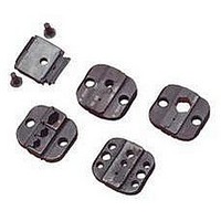
2.2. Pinned Dies
2
Pneumatic Head Assembly 679304-1
of 5
5. Check die alignment by allowing the crimping
jaws to spring shut. If dies are properly aligned,
tighten the die retaining screws.
6. To remove the dies from the head assembly,
loosen the pan head screws and slide dies out of
the crimping jaws.
1. Open crimping jaws by squeezing rollers
together. Install anvil die into crimping jaw. The die
should be oriented so that the chamfers are
positioned toward the front of the head assembly
and the die markings are facing outward. See
Figure 3.
2. Insert bushing into the crimping jaw. Insert two
die retaining pins and the short die retaining screw
into the crimping jaw and through the anvil die.
Tighten the screw just enough to hold the die in
place. See Figure 3.
3. Install crimper die into the crimping jaw, as
shown in Figure 3. The die should be oriented so
that the chamfers are positioned toward the front of
the head assembly and the die markings are facing
outward. See Figure 3.
4. Insert bushing into the crimping jaw. Insert two
die retaining pins and the long die retaining screw
into the crimping jaw and through the crimper die.
Tighten the retaining screw just enough to hold the
die in place. See Figure 3.
5. Check die alignment by allowing the crimping
jaws to spring shut. If dies are properly aligned,
tighten the die retaining screws.
(Figure 3)
Pan Head
Screw(s)
Crimper Die
Tyco Electronics Corporation
Figure 2
3. HEAD ASSEMBLY INSTALLATION AND REMOVAL
3.1. Installation
DANGER
6. Install locator assembly onto the long retaining
screw and secure it with the hex nut. See Figure 3.
7. To remove the dies from the crimping jaws,
loosen the die retaining screws and slide the dies
out of the crimping jaws.
NOTE
1. Insert head assembly into tool holder assembly
of pneumatic tooling assembly, as shown in
Figure 1.
2. After the head assembly is properly aligned,
insert and tighten the quick pins provided with the
pneumatic tooling assembly. Refer to Figure 1.
NOTE
i
i
Bushings
Pneumatic Head
Assembly
679304-1
Anvil
Die
Disconnect pneumatic tooling assembly from air
supply before installing the head assembly.
Certain precautions should be taken by the
operator to avoid personal injury or damage to
the pneumatic tool. Refer to the instruction sheet
supplied with the pneumatic tool for operation
and safety precautions.
Tyco Electronics recommends using Loctite No.
242 removable thread-lock or equivalent to
prevent the quick pins from loosening.
Contact Crimp Section
Positioned Toward
Front of Adapter
Installing Shouldered Dies
408-4070
Rev
C