58238-1 Tyco Electronics, 58238-1 Datasheet

DIE SET SHELL SIZE 4-5 .375-.435

58238-1

Manufacturer Part Number
58238-1
Description
DIE SET SHELL SIZE 4-5 .375-.435
Manufacturer
Tyco Electronics
Series
AMPLIMITE®r
Type
Crimpersr
Datasheets

Specifications of 58238-1

Connector Type
Ferrule
Crimp Handle
543344-1
Crimp Or Cable Size
0.375" ~ 0.435" (9.53mm~11.05mm) Dia
Lead Free Status / RoHS Status
Not applicable / Not applicable
PROPER USE GUIDELINES
1. INTRODU TION
This instruction sheet covers the use and
maintenance of Crimping Die Assembly 58238–1,
which is designed to be used in Hand Crimping Tool
Frame Assembly 543344–1, or in Pneumatic Power
Unit 312522–3 equipped with Die Holder Assembly
58449–1. The die assembly crimps a ferrule onto
round shielded cable used with Shielded AMPLIMITE
Connectors.
Tyco Electronics Catalog 82068 provides a guide for
cable–to–connector and ferrule selection. Read these
and all referenced materials before using the die
assembly.
Reasons for reissue are provided in Section 7,
REVISION SUMMARY.
NOTE
inches in brackets]. Figures are not drawn to
scale.
easurements are in millimeters [followed by
Figure 1
for AMPLIMITE* onnectors
rimping Die Assembly 58238-1
2. DES RIPTION
The die assembly consists of an indenter (stationary
die) which has chamfered corners and an anvil
(moving die) which has square corners. When mated,
the dies form two crimping sections: the braid and the
insulation. The braid section crimps the front part of
the ferrule onto the cable shield and the cable outlet
of the connector shield assembly, and simultaneously,
the insulation section crimps the back part of the
ferrule onto the cable insulation. See Figure 1.
The ferrule, which is ordered separately from the
AMPLIMITE connector, is sized according to the
insulation diameter of the cable. The die assembly is
marked with the cable insulation diameter range.
3. DIE INSTALLATION
The die assembly is designed to fit securely into the
tool by upper and lower die holder plates; each die is
held in by a single screw. To install the die assembly,
refer to the instructions packaged with the tool:
4. RIMPING PRO EDURE
Assemble the connector by referring to instruction
sheet 408–9010. Make sure the ferrule is over the
connector shield cable outlet and butted against the
shield body. Then, proceed as follows:
AUTION
1. Place the ferrule on the stationary die, with the
cable extending out the back side of the die. Make
sure that the front part of the ferrule is positioned in
the braid section and the back part of the ferrule is
positioned in the insulation section. See Figure 2.
2. If using the hand tool, close and latch the tool
head in place.
3. Make certain that the ferrule is maintained in
proper position, and close tool handles completely
(or actuate dies in pneumatic applicator die holder)
to complete the crimp.
!
408–9315
408–9721
409–5822
Connector body must be clear of dies.
Hand Crimping Tool Frame
Assembly 543344–1
Die Holder Assembly 58449–1
Pneumatic Power Unit 312522–3
www.tycoelectronics.com
408-9243
1

58238-1 Summary of contents

Page 1

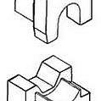
... NOTE inches in brackets]. Figures are not drawn to scale. Reasons for reissue are provided in Section 7, REVISION SUMMARY. rimping Die Assembly 58238-1 for AMPLIMITE* onnectors 2. DES RIPTION The die assembly consists of an indenter (stationary die) which has chamfered corners and an anvil (moving die) which has square corners. When mated, the dies form two crimping sections: the braid and the insulation ...

Page 2

... Crimping Die Assembly 58238-1 CABLE CONNECTO BODY CLEA OF DIES 4. Remove connector from die assembly and inspect the crimped ferrule according to the requirements outlined in the appropriate application specification: 114–40008 AMPLIMITE HDE–20 Connector Shielding Hardware Kits With and Without Enclosure 114–40030 AMPLIMITE HDP– ...

Page 3

... If damage is evident, the dies must be replaced. See Section 6, REPLACEMENT PARTS. This inspection requires the use of plug gages conforming to the dimensions provided in Figure 4. Tyco Electronics does not manufacture or market these gages. For each crimping section, proceed as follows: Rev NO-GO DIM. ...

Page 4

... Crimping Die Assembly 58238-1 ITEM PART NUMBER 6. REPLACEMENT PARTS The parts listed in Figure 5 are customer– replaceable. A complete inventory can be stocked and controlled to prevent lost time when replacement of parts is necessary. Order replacement parts through your Tyco Electronics representative, or call 1–800–526–5142, or send a facsimile of your purchase order to 717– ...