5-1437514-5 Tyco Electronics, 5-1437514-5 Datasheet - Page 4
5-1437514-5
Manufacturer Part Number
5-1437514-5
Description
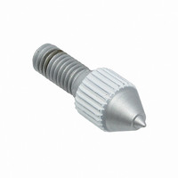
TOOL HAND SPRING LOADED
Manufacturer
Tyco Electronics
Series
HOLTITEr
Type
Hand Tool, Spring Loadedr
Specifications of 5-1437514-5
Product
Crimping, Stripping & Cutting Tools & Drills
Lead Free Status / RoHS Status
Not applicable / Not applicable


3.5. Socket Insertion
3.6. Checking Installed Socket
Once the socket is installed, verification may be made to a correct installation according to the information and
dimensions provided in Figures 2 and 4.
4
of 7
A. Hole Size Inspection
Using the red NO–GO gage, part number 5–1437514–1, end of the tool provided in the AUGAT HOLTITE
Printed Wiring Contact Kit, check to ensure the hole dimensions are correct. If not, rework may be
necessary or socket selection may need to be re–checked.
B. Insertion
Sockets are inserted into the pc board using a spring loaded hand tool, a pneumatic hand tool system,
flat–rock press–in tooling, or commercially available vibratory/vacuum systems using fully automatic
machines. Two different tips may be used for socket insertion into the pc board. The blue tip is used for
the 5P, 14P, and 27P series sockets. The other insertion tip is white and is used for the 6P, 8P, and 12P
series sockets. Refer to Section 5, TOOLING for specific related tooling part numbers.
A. Referee Test
Inspection may reveal that some of the hole diameters are at the high limit of the tolerance. If this marginal
condition occurs, a “referee test” should be performed to determine if the holes are suitable for 5P
AUGAT HOLTITE Socket insertion.
Selectively load the sockets into the suspect holes and perform a push–out test using an adequate axial
force gauge (e.g., a hand held CHATILLON
only in an axial direction. Socket retention forces will vary with each application due to differences in
socket population density, substrate materials, and number of PC layers. The minimum acceptable
push–out force for all 5P AUGAT HOLTITE Sockets is [4 lbs.] (conforming to MIL–S–83505/6).
B. Insertion Verification
Tyco Electronics suggests verifying that the sockets have been loaded into all of the desired locations.
This procedure could be accomplished visually or with any type of available automatic non–contacting
inspection system.
For visual inspection, place a light source under the pc board an examine the holes form above. A small
point of light indicates the socket is present. A large point of light indicates the socket may be missing. The
light pattern may be compared to a chart showing socket locations.
Plated Through
Hole
Socket
Area Dia.
Finished
Diameter
Hole
AUGAT HOLTITE Sockets
t
Force Gauge). Force should be applied to the socket fingers
Figure 4
Glass Epoxy
Substrate
Vertical Profile
Dimension (Max)
114-13033
Rev
A