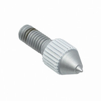
5-1437514-5 Tyco Electronics, 5-1437514-5 Datasheet - Page 5

5-1437514-5
Manufacturer Part Number
5-1437514-5
Description
TOOL HAND SPRING LOADED
Manufacturer
Tyco Electronics
Series
HOLTITEr
Type
Hand Tool, Spring Loadedr
Specifications of 5-1437514-5
Product
Crimping, Stripping & Cutting Tools & Drills
Lead Free Status / RoHS Status
Not applicable / Not applicable
Both AUGAT HOLTITE Sockets and soldered components may be loaded on a pc board. However, either the
AUGAT HOLTITE Sockets or their respective plated through holes must be masked to avoid being filled with
solder during wave soldering. If the socket can be contained within the pc board, it may be loaded first, and
then masked with heat–resistant tape or liquid solder mask prior to soldering to other components. If the socket
would protrude through the pc board, the appropriate plated through holes should be masked and wave
soldering performed first. Then, the masking is to be removed, and the AUGAT HOLTITE Sockets may be
installed. See Figure 5.
If a socket has been damaged, it must be removed and replaced with a new one. In order to remove a
damaged socket, lay the circuit board flat, circuit fingers up on a suitable backing material such as a dense
foam board or pad. Place a drill blank on top of the socket fingers, making sure it is properly aligned, and tap it
gently with a small hammer until it releases from the pc board. See Figure 6.
It may be necessary, if the socket fingers are damaged, to break off the individual finger elements before
removing the socket barrel using the previous technique. Installation of a single replacement socket can then
be accomplished.
These sockets are qualified to MIL–S–83505/6D. However, they are not required to be Recognized by
Underwriters Laboratories Inc. (UL); or Certified to CSA International.
Tyco Electronics has existing tooling and tooling concepts for applying these sockets. Part numbers of
available tooling and the applicable instructional material for each is provided in Figure 7.
Rev
S
S
S
For the alternate method, use an opaque inspection template drilled in a pattern matching the socket
locations. There should be no large points of light with the template in place. A loading mask used in
conjunction with a mass loading machine will serve this purpose.
2.39 [.094]
A pc board support must be used to prevent bowing of the pc board during insertion of the sockets. It
should have a flat surface with holes or a channel large enough to receive the sockets during installation.
The insertion portion of the tool is designed to remove the sockets from their respective carrier cards
and selectively insert them into the plated–through hole on the pc board. Individual pressing and seating
is then accomplished using the correct insertion tip and hand tool.
The pneumatic tooling system is designed to individually seat the sockets after they have been inserted
into the plated–through hole on the pc board. The tip of the pneumatic hand tool is inserted into the
socket and the impact button is depressed. The socket is accurately seated into the plated–through
hole. Pressure adjustments and variable tip sizes on the pneumatic hand tool allow this system to work
with any size socket.
3.45 [.136]
(No. 62) 0.97 [.038]
5P, 14P, 27P
3.45 [.136]
Figure 5
Figure 6
3.96 [.156]
(No. 54) 1.40 [.055]
6P, 8P
2.39 [.094]
(No. 47) 1.99 [.078]
12P
2.39 [.094]
of 7


