06035C104KAT2A AVX Corporation, 06035C104KAT2A Datasheet - Page 12
06035C104KAT2A
Manufacturer Part Number
06035C104KAT2A
Description
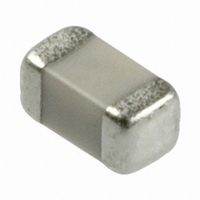
CAP CER .10UF 50V X7R 10% 0603
Manufacturer
AVX Corporation
Specifications of 06035C104KAT2A
Capacitance
0.1µF
Tolerance
±10%
Package / Case
0603 (1608 Metric)
Voltage - Rated
50V
Temperature Coefficient
X7R
Mounting Type
Surface Mount, MLCC
Operating Temperature
-55°C ~ 125°C
Applications
General Purpose
Size / Dimension
0.063" L x 0.031" W (1.60mm x 0.80mm)
Thickness
0.90mm Max
Voltage Rating
50 Volts
Operating Temperature Range
- 55 C to + 125 C
Temperature Coefficient / Code
X7R
Product
General Type MLCCs
Dimensions
0.81 mm W x 1.6 mm L
Dissipation Factor Df
10
Termination Style
SMD/SMT
Dielectric Characteristic
X7R
Capacitance Tolerance
± 10%
Capacitor Case Style
0603
No. Of Pins
2
Capacitor Mounting
SMD
Rohs Compliant
Yes
Case Size
0603
Material, Element
Ceramic
Termination
SMT
Voltage, Rating
50 VDC
Lead Free Status / RoHS Status
Lead free / RoHS Compliant
Features
-
Ratings
-
Lead Spacing
-
Lead Free Status / Rohs Status
Lead free / RoHS Compliant
Other names
06035C104KAT2A
478-5052-2
478-5052-2
Available stocks
Company
Part Number
Manufacturer
Quantity
Price
Company:

Part Number:
06035C104KAT2A
Manufacturer:
AVX
Quantity:
760 000


General Description
Effects of Time – Class 2 ceramic capacitors change
capacitance and dissipation factor with time as well as tem-
perature, voltage and frequency. This change with time is
known as aging. Aging is caused by a gradual re-alignment
of the crystalline structure of the ceramic and produces an
exponential loss in capacitance and decrease in dissipation
factor versus time. A typical curve of aging rate for semi-
stable ceramics is shown in Figure 6.
If a Class 2 ceramic capacitor that has been sitting on the
shelf for a period of time, is heated above its curie point,
(125°C for 4 hours or 150°C for
will de-age and return to its initial capacitance and dissi-
pation factor readings. Because the capacitance changes
rapidly, immediately after de-aging, the basic capacitance
measurements are normally referred to a time period some-
time after the de-aging process. Various manufacturers use
different time bases but the most popular one is one day
or twenty-four hours after “last heat.” Change in the aging
curve can be caused by the application of voltage and
other stresses. The possible changes in capacitance due to
de-aging by heating the unit explain why capacitance
changes are allowed after test, such as temperature cycling,
moisture resistance, etc., in MIL specs. The application of
high voltages such as dielectric withstanding voltages also
-2.5
-7.5
-10
2.5
-5
+10
+20
-10
-20
-30
0
0
-55 -35
Typical Cap. Change vs. Temperature
Typical Cap. Change vs. D.C. Volts
Temperature Degrees Centigrade
25%
-15
Percent Rated Volts
+5
Figure 4
Figure 5
X7R
X7R
+25 +45 +65 +85 +105 +125
50%
0VDC
1
⁄
2
hour will suffice) the part
75%
100%
tends to de-age capacitors and is why re-reading of capaci-
tance after 12 or 24 hours is allowed in military specifica-
tions after dielectric strength tests have been performed.
Effects of Frequency – Frequency affects capacitance
and impedance characteristics of capacitors. This effect is
much more pronounced in high dielectric constant ceramic
formulation than in low K formulations. AVX’s SpiCap soft-
ware generates impedance, ESR, series inductance, series
resonant frequency and capacitance all as functions of
frequency, temperature and DC bias for standard chip sizes
and styles. It is available free from AVX and can be down-
loaded for free from AVX website: www.avx.com.
+1.5
-3.0
-4.5
-1.5
-6.0
-7.5
0
1
Characteristic
C0G (NP0)
X7R, X5R
Y5V
Typical Curve of Aging Rate
10
100
Figure 6
Max. Aging Rate %/Decade
X7R
Hours
1000 10,000 100,000
None
2
7
67
Related parts for 06035C104KAT2A
Image
Part Number
Description
Manufacturer
Datasheet
Request
R

Part Number:
Description:
Manufacturer:
AVX Corporation
Datasheet:
Part Number:
Description:
Manufacturer:
AVX Corporation
Datasheet:
Part Number:
Description:
Manufacturer:
AVX Corporation
Datasheet:
Part Number:
Description:
Manufacturer:
AVX Corporation
Datasheet:
Part Number:
Description:
Manufacturer:
AVX Corporation
Datasheet: