P87C554SBAA,512 NXP Semiconductors, P87C554SBAA,512 Datasheet - Page 40
P87C554SBAA,512
Manufacturer Part Number
P87C554SBAA,512
Description
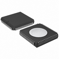
IC 80C51 MCU 16K OTP 64-PLCC
Manufacturer
NXP Semiconductors
Series
87Cr
Specifications of P87C554SBAA,512
Core Processor
8051
Core Size
8-Bit
Speed
16MHz
Connectivity
EBI/EMI, I²C, UART/USART
Peripherals
POR, PWM, WDT
Number Of I /o
40
Program Memory Size
16KB (16K x 8)
Program Memory Type
OTP
Ram Size
512 x 8
Voltage - Supply (vcc/vdd)
2.7 V ~ 5.5 V
Data Converters
A/D 8x10b
Oscillator Type
Internal
Operating Temperature
0°C ~ 70°C
Package / Case
68-PLCC
Cpu Family
87C
Device Core
80C51
Device Core Size
8b
Frequency (max)
16MHz
Interface Type
I2C/UART
Total Internal Ram Size
512Byte
# I/os (max)
40
Number Of Timers - General Purpose
3
Operating Supply Voltage (typ)
5V
Operating Supply Voltage (max)
5.5V
Operating Supply Voltage (min)
4.5V
On-chip Adc
7-chx10-bit
Instruction Set Architecture
CISC
Operating Temp Range
0C to 70C
Operating Temperature Classification
Commercial
Mounting
Surface Mount
Pin Count
68
Package Type
PLCC
Processor Series
P87C5x
Core
80C51
Data Bus Width
8 bit
Data Ram Size
512 B
Maximum Clock Frequency
16 MHz
Number Of Programmable I/os
40
Number Of Timers
3
Operating Supply Voltage
2.7 V to 5.5 V
Maximum Operating Temperature
+ 70 C
Mounting Style
SMD/SMT
3rd Party Development Tools
PK51, CA51, A51, ULINK2
Minimum Operating Temperature
0 C
Lead Free Status / RoHS Status
Lead free / RoHS Compliant
Eeprom Size
-
Lead Free Status / Rohs Status
Compliant
Other names
568-1254-5
935263385512
P87C554SBAA
935263385512
P87C554SBAA
Available stocks
Company
Part Number
Manufacturer
Quantity
Price
Company:

Part Number:
P87C554SBAA,512
Manufacturer:
NXP Semiconductors
Quantity:
10 000


detailed in Table 6. After a repeated start condition (state 10H). SIO1
Philips Semiconductors
More Information on SIO1 Operating Modes: The four operating
modes are:
– Master Transmitter
– Master Receiver
– Slave Receiver
– Slave Transmitter
Data transfers in each mode of operation are shown in Figures
40–43. These figures contain the following abbreviations:
Abbreviation
S
SLA
R
W
A
A
Data
P
In Figures 40-43, circles are used to indicate when the serial
interrupt flag is set. The numbers in the circles show the status code
held in the S1STA register. At these points, a service routine must
be executed to continue or complete the serial transfer. These
service routines are not critical since the serial transfer is suspended
until the serial interrupt flag is cleared by software.
When a serial interrupt routine is entered, the status code in S1STA
is used to branch to the appropriate service routine. For each status
code, the required software action and details of the following serial
transfer are given in Tables 6-10.
Master Transmitter Mode: In the master transmitter mode, a
number of data bytes are transmitted to a slave receiver (see
Figure 40). Before the master transmitter mode can be entered,
S1CON must be initialized as follows:
S1CON (D8H)
CR0, CR1, and CR2 define the serial bit rate. ENS1 must be set to
logic 1 to enable SIO1. If the AA bit is reset, SIO1 will not
acknowledge its own slave address or the general call address in
the event of another device becoming master of the bus. In other
words, if AA is reset, SIO0 cannot enter a slave mode. STA, STO,
and SI must be reset.
The master transmitter mode may now be entered by setting the
STA bit using the SETB instruction. The SIO1 logic will now test the
I
free. When a START condition is transmitted, the serial interrupt flag
(SI) is set, and the status code in the status register (S1STA) will be
08H. This status code must be used to vector to an interrupt service
routine that loads S1DAT with the slave address and the data
direction bit (SLA+W). The SI bit in S1CON must then be reset
before the serial transfer can continue.
When the slave address and the direction bit have been transmitted
and an acknowledgment bit has been received, the serial interrupt
flag (SI) is set again, and a number of status codes in S1STA are
possible. There are 18H, 20H, or 38H for the master mode and also
68H, 78H, or B0H if the slave mode was enabled (AA = logic 1). The
appropriate action to be taken for each of these status codes is
2002 Mar 25
2
C bus and generate a start condition as soon as the bus becomes
80C51 8-bit microcontroller – 12 clock operation
16K/512 OTP/RAM, 8 channel 10-bit A/D, I
capture/compare, high I/O
rate
CR2
bit
7
Start condition
7-bit slave address
Read bit (high level at SDA)
Write bit (low level at SDA)
Acknowledge bit (low level at SDA)
Not acknowledge bit (high level at SDA)
8-bit data byte
Stop condition
ENS1
6
1
Explanation
STA
5
0
STO
4
0
SI
0
3
AA
X
2
CR1
1
bit rate
2
CR0
C, PWM,
0
38
affected by the serial transfer and are not referred to in Table 7. After
may switch to the master receiver mode by loading S1DAT with
SLA+R).
Master Receiver Mode: In the master receiver mode, a number of
data bytes are received from a slave transmitter (see Figure 41).
The transfer is initialized as in the master transmitter mode. When
the start condition has been transmitted, the interrupt service routine
must load S1DAT with the 7-bit slave address and the data direction
bit (SLA+R). The SI bit in S1CON must then be cleared before the
serial transfer can continue.
When the slave address and the data direction bit have been
transmitted and an acknowledgment bit has been received, the
serial interrupt flag (SI) is set again, and a number of status codes in
S1STA are possible. These are 40H, 48H, or 38H for the master
mode and also 68H, 78H, or B0H if the slave mode was enabled
(AA = logic 1). The appropriate action to be taken for each of these
status codes is detailed in Table 7. ENS1, CR1, and CR0 are not
a repeated start condition (state 10H), SIO1 may switch to the
master transmitter mode by loading S1DAT with SLA+W.
Slave Receiver Mode: In the slave receiver mode, a number of
data bytes are received from a master transmitter (see Figure 42).
To initiate the slave receiver mode, S1ADR and S1CON must be
loaded as follows:
The upper 7 bits are the address to which SIO1 will respond when
addressed by a master. If the LSB (GC) is set, SIO1 will respond to
the general call address (00H); otherwise it ignores the general call
address.
S1CON (D8H)
CR0, CR1, and CR2 do not affect SIO1 in the slave mode. ENS1
must be set to logic 1 to enable SIO1. The AA bit must be set to
enable SIO1 to acknowledge its own slave address or the general
call address. STA, STO, and SI must be reset.
When S1ADR and S1CON have been initialized, SIO1 waits until it
is addressed by its own slave address followed by the data direction
bit which must be “0” (W) for SIO1 to operate in the slave receiver
mode. After its own slave address and the W bit have been
received, the serial interrupt flag (I) is set and a valid status code
can be read from S1STA. This status code is used to vector to an
interrupt service routine, and the appropriate action to be taken for
each of these status codes is detailed in Table 8. The slave receiver
mode may also be entered if arbitration is lost while SIO1 is in the
master mode (see status 68H and 78H).
If the AA bit is reset during a transfer, SIO1 will return a not
acknowledge (logic 1) to SDA after the next received data byte.
While AA is reset, SIO1 does not respond to its own slave address
or a general call address. However, the I
and address recognition may be resumed at any time by setting AA.
This means that the AA bit may be used to temporarily isolate SIO1
from the I
S1ADR (DBH)
2
C bus.
CR2
X
7
X
7
X
ENS1
6
1
6
X
5
STA
own slave address
5
0
4
X
STO
4
0
2
C bus is still monitored
3
X
SI
0
3
AA
2
X
2
1
P87C554
CR1
Product data
X
1
X
1
CR0
GC
0
X
0
Related parts for P87C554SBAA,512
Image
Part Number
Description
Manufacturer
Datasheet
Request
R

Part Number:
Description:
NXP Semiconductors designed the LPC2420/2460 microcontroller around a 16-bit/32-bitARM7TDMI-S CPU core with real-time debug interfaces that include both JTAG andembedded trace
Manufacturer:
NXP Semiconductors
Datasheet:

Part Number:
Description:
NXP Semiconductors designed the LPC2458 microcontroller around a 16-bit/32-bitARM7TDMI-S CPU core with real-time debug interfaces that include both JTAG andembedded trace
Manufacturer:
NXP Semiconductors
Datasheet:
Part Number:
Description:
NXP Semiconductors designed the LPC2468 microcontroller around a 16-bit/32-bitARM7TDMI-S CPU core with real-time debug interfaces that include both JTAG andembedded trace
Manufacturer:
NXP Semiconductors
Datasheet:
Part Number:
Description:
NXP Semiconductors designed the LPC2470 microcontroller, powered by theARM7TDMI-S core, to be a highly integrated microcontroller for a wide range ofapplications that require advanced communications and high quality graphic displays
Manufacturer:
NXP Semiconductors
Datasheet:
Part Number:
Description:
NXP Semiconductors designed the LPC2478 microcontroller, powered by theARM7TDMI-S core, to be a highly integrated microcontroller for a wide range ofapplications that require advanced communications and high quality graphic displays
Manufacturer:
NXP Semiconductors
Datasheet:
Part Number:
Description:
The Philips Semiconductors XA (eXtended Architecture) family of 16-bit single-chip microcontrollers is powerful enough to easily handle the requirements of high performance embedded applications, yet inexpensive enough to compete in the market for hi
Manufacturer:
NXP Semiconductors
Datasheet:
Part Number:
Description:
The XA-S3 device is a member of Philips Semiconductors? XA(eXtended Architecture) family of high performance 16-bitsingle-chip microcontrollers
Manufacturer:
NXP Semiconductors
Datasheet:

Part Number:
Description:
The NXP BlueStreak LH75401/LH75411 family consists of two low-cost 16/32-bit System-on-Chip (SoC) devices
Manufacturer:
NXP Semiconductors
Datasheet:
Part Number:
Description:
The NXP LPC3130/3131 combine an 180 MHz ARM926EJ-S CPU core, high-speed USB2
Manufacturer:
NXP Semiconductors
Datasheet:
Part Number:
Description:
The NXP LPC3141 combine a 270 MHz ARM926EJ-S CPU core, High-speed USB 2
Manufacturer:
NXP Semiconductors
Part Number:
Description:
The NXP LPC3143 combine a 270 MHz ARM926EJ-S CPU core, High-speed USB 2
Manufacturer:
NXP Semiconductors

Part Number:
Description:
The NXP LPC3152 combines an 180 MHz ARM926EJ-S CPU core, High-speed USB 2
Manufacturer:
NXP Semiconductors
Part Number:
Description:
The NXP LPC3154 combines an 180 MHz ARM926EJ-S CPU core, High-speed USB 2
Manufacturer:
NXP Semiconductors

Part Number:
Description:
Standard level N-channel enhancement mode Field-Effect Transistor (FET) in a plastic package using NXP High-Performance Automotive (HPA) TrenchMOS technology
Manufacturer:
NXP Semiconductors
Datasheet: