C8051F321-GMR Silicon Laboratories Inc, C8051F321-GMR Datasheet - Page 18
C8051F321-GMR
Manufacturer Part Number
C8051F321-GMR
Description
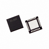
IC 8051 MCU 16K FLASH 28MLP
Manufacturer
Silicon Laboratories Inc
Series
C8051F32xr
Specifications of C8051F321-GMR
Core Processor
8051
Core Size
8-Bit
Speed
25MHz
Connectivity
SMBus (2-Wire/I²C), SPI, UART/USART, USB
Peripherals
Brown-out Detect/Reset, POR, PWM, Temp Sensor, WDT
Number Of I /o
21
Program Memory Size
16KB (16K x 8)
Program Memory Type
FLASH
Ram Size
2.25K x 8
Voltage - Supply (vcc/vdd)
2.7 V ~ 3.6 V
Data Converters
A/D 13x10b
Oscillator Type
Internal
Operating Temperature
-40°C ~ 85°C
Package / Case
28-VQFN Exposed Pad, 28-HVQFN, 28-SQFN, 28-DHVQFN
Processor Series
C8051F3x
Core
8051
Data Bus Width
8 bit
Data Ram Size
2.25 KB
Interface Type
I2C, SMBus, SPI, UART, USB
Maximum Clock Frequency
25 MHz
Number Of Programmable I/os
21
Number Of Timers
4
Maximum Operating Temperature
+ 85 C
Mounting Style
SMD/SMT
3rd Party Development Tools
PK51, CA51, A51, ULINK2
Development Tools By Supplier
C8051F320DK
Minimum Operating Temperature
- 40 C
On-chip Adc
10 bit, 13 Channel / 10 bit, 7 Channel
Package
28MLP
Device Core
8051
Family Name
C8051F321
Maximum Speed
25 MHz
Operating Supply Voltage
3.3 V
For Use With
336-1480 - DAUGHTER CARD TOOLSTCK C8051F321336-1449 - ADAPTER PROGRAM TOOLSTICK F321336-1260 - DEV KIT FOR C8051F320/F321
Lead Free Status / RoHS Status
Lead free / RoHS Compliant
Eeprom Size
-
Lead Free Status / Rohs Status
Details
Available stocks
Company
Part Number
Manufacturer
Quantity
Price

Part Number:
C8051F321-GMR
Manufacturer:
SILICON LABS/èٹ¯ç§‘
Quantity:
20 000


C8051F320/1
1.1.
1.1.1. Fully 8051 Compatible
The C8051F320/1 family utilizes Silicon Labs' proprietary CIP-51 microcontroller core. The CIP-51 is fully
compatible with the MCS-51™ instruction set; standard 803x/805x assemblers and compilers can be used
to develop software. The CIP-51 core offers all the peripherals included with a standard 8052, including
four 16-bit counter/timers, a full-duplex UART with extended baud rate configuration, an enhanced SPI
port, 2304 bytes of on-chip RAM, 128 byte Special Function Register (SFR) address space, and 25/21 I/O
pins.
1.1.2. Improved Throughput
The CIP-51 employs a pipelined architecture that greatly increases its instruction throughput over the stan-
dard 8051 architecture. In a standard 8051, all instructions except for MUL and DIV take 12 or 24 system
clock cycles to execute with a maximum system clock of 12-to-24 MHz. By contrast, the CIP-51 core exe-
cutes 70% of its instructions in one or two system clock cycles, with only four instructions taking more than
four system clock cycles.
The CIP-51 has a total of 109 instructions. The table below shows the total number of instructions that
require each execution time.
1.1.3. Additional Features
The C8051F320/1 SoC family includes several key enhancements to the CIP-51 core and peripherals to
improve performance and ease of use in end applications.
The extended interrupt handler provides 16 interrupt sources into the CIP-51 (as opposed to 7 for the stan-
dard 8051), allowing numerous analog and digital peripherals to interrupt the controller. An interrupt driven
system requires less intervention by the MCU, giving it more effective throughput. The extra interrupt
sources are very useful when building multi-tasking, real-time systems.
Nine reset sources are available: power-on reset circuitry (POR), an on-chip VDD monitor (forces reset
when power supply voltage drops below V
(USB bus reset or a VBUS transition), a Watchdog Timer, a Missing Clock Detector, a voltage level detec-
tion from Comparator0, a forced software reset, an external reset pin, and an errant Flash read/write pro-
tection circuit. Each reset source except for the POR, Reset Input Pin, or Flash error may be disabled by
the user in software. The WDT may be permanently enabled in software after a power-on reset during
MCU initialization.
The internal oscillator is factory calibrated to 12 MHz ±1.5%, and the internal oscillator period may be user
programmed in ~0.25% increments. A clock recovery mechanism allows the internal oscillator to be used
with the 4x Clock Multiplier as the USB clock source in Full Speed mode; the internal oscillator can also be
used as the USB clock source in Low Speed mode. External oscillators may also be used with the 4x Clock
Multiplier. An external oscillator drive circuit is also included, allowing an external crystal, ceramic resona-
tor, capacitor, RC, or CMOS clock source to generate the system clock. The system clock may be config-
ured to use the internal oscillator, external oscillator, or the Clock Multiplier output divided by 2. If desired,
the system clock source may be switched on-the-fly between oscillator sources. An external oscillator can
be extremely useful in low power applications, allowing the MCU to run from a slow (power saving) exter-
nal clock source, while periodically switching to the internal oscillator as needed.
18
Number of Instructions
Clocks to Execute
CIP-51™ Microcontroller Core
26
1
50
2
RST
as given in Table 10.1 on page 105), the USB controller
2/3
Rev. 1.4
5
14
3
3/4
7
4
3
4/5
1
5
2
8
1
Related parts for C8051F321-GMR
Image
Part Number
Description
Manufacturer
Datasheet
Request
R

Part Number:
Description:
SMD/C°/SINGLE-ENDED OUTPUT SILICON OSCILLATOR
Manufacturer:
Silicon Laboratories Inc
Part Number:
Description:
Manufacturer:
Silicon Laboratories Inc
Datasheet:
Part Number:
Description:
N/A N/A/SI4010 AES KEYFOB DEMO WITH LCD RX
Manufacturer:
Silicon Laboratories Inc
Datasheet:
Part Number:
Description:
N/A N/A/SI4010 SIMPLIFIED KEY FOB DEMO WITH LED RX
Manufacturer:
Silicon Laboratories Inc
Datasheet:
Part Number:
Description:
N/A/-40 TO 85 OC/EZLINK MODULE; F930/4432 HIGH BAND (REV E/B1)
Manufacturer:
Silicon Laboratories Inc
Part Number:
Description:
EZLink Module; F930/4432 Low Band (rev e/B1)
Manufacturer:
Silicon Laboratories Inc
Part Number:
Description:
I°/4460 10 DBM RADIO TEST CARD 434 MHZ
Manufacturer:
Silicon Laboratories Inc
Part Number:
Description:
I°/4461 14 DBM RADIO TEST CARD 868 MHZ
Manufacturer:
Silicon Laboratories Inc
Part Number:
Description:
I°/4463 20 DBM RFSWITCH RADIO TEST CARD 460 MHZ
Manufacturer:
Silicon Laboratories Inc
Part Number:
Description:
I°/4463 20 DBM RADIO TEST CARD 868 MHZ
Manufacturer:
Silicon Laboratories Inc
Part Number:
Description:
I°/4463 27 DBM RADIO TEST CARD 868 MHZ
Manufacturer:
Silicon Laboratories Inc
Part Number:
Description:
I°/4463 SKYWORKS 30 DBM RADIO TEST CARD 915 MHZ
Manufacturer:
Silicon Laboratories Inc
Part Number:
Description:
N/A N/A/-40 TO 85 OC/4463 RFMD 30 DBM RADIO TEST CARD 915 MHZ
Manufacturer:
Silicon Laboratories Inc
Part Number:
Description:
I°/4463 20 DBM RADIO TEST CARD 169 MHZ
Manufacturer:
Silicon Laboratories Inc