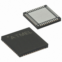
ATMEGA644P-A15MZ Atmel, ATMEGA644P-A15MZ Datasheet - Page 58

ATMEGA644P-A15MZ
Manufacturer Part Number
ATMEGA644P-A15MZ
Description
MCU AVR 64KB FLASH 16MHZ 44QFN
Manufacturer
Atmel
Series
AVR® ATmegar
Specifications of ATMEGA644P-A15MZ
Package / Case
44-VQFN Exposed Pad
Voltage - Supply (vcc/vdd)
2.7 V ~ 5.5 V
Operating Temperature
-40°C ~ 125°C
Speed
16MHz
Number Of I /o
32
Eeprom Size
2K x 8
Core Processor
AVR
Program Memory Type
FLASH
Ram Size
4K x 8
Program Memory Size
64KB (64K x 8)
Data Converters
A/D 8x10b
Oscillator Type
Internal
Peripherals
Brown-out Detect/Reset, POR, PWM, WDT
Connectivity
I²C, SPI, UART/USART
Core Size
8-Bit
Lead Free Status / RoHS Status
Lead free / RoHS Compliant
Available stocks
Company
Part Number
Manufacturer
Quantity
Price
Company:
Part Number:
ATMEGA644P-A15MZ
Manufacturer:
ATMEL
Quantity:
3 500
Part Number:
ATMEGA644P-A15MZ
Manufacturer:
ATMEL/爱特梅尔
Quantity:
20 000
- Current page: 58 of 377
- Download datasheet (7Mb)
9.3.2
58
ATmega164P/324P/644P
WDTCSR – Watchdog Timer Control Register
• Bit 7 - WDIF: Watchdog Interrupt Flag
This bit is set when a time-out occurs in the Watchdog Timer and the Watchdog Timer is config-
ured for interrupt. WDIF is cleared by hardware when executing the corresponding interrupt
handling vector. Alternatively, WDIF is cleared by writing a logic one to the flag. When the I-bit in
SREG and WDIE are set, the Watchdog Time-out Interrupt is executed.
• Bit 6 - WDIE: Watchdog Interrupt Enable
When this bit is written to one and the I-bit in the Status Register is set, the Watchdog Interrupt is
enabled. If WDE is cleared in combination with this setting, the Watchdog Timer is in Interrupt
Mode, and the corresponding interrupt is executed if time-out in the Watchdog Timer occurs.
If WDE is set, the Watchdog Timer is in Interrupt and System Reset Mode. The first time-out in
the Watchdog Timer will set WDIF. Executing the corresponding interrupt vector will clear WDIE
and WDIF automatically by hardware (the Watchdog goes to System Reset Mode). This is use-
ful for keeping the Watchdog Timer security while using the interrupt. To stay in Interrupt and
System Reset Mode, WDIE must be set after each interrupt. This should however not be done
within the interrupt service routine itself, as this might compromise the safety-function of the
Watchdog System Reset mode. If the interrupt is not executed before the next time-out, a Sys-
tem Reset will be applied.
Table 9-1.
• Bit 4 - WDCE: Watchdog Change Enable
This bit is used in timed sequences for changing WDE and prescaler bits. To clear the WDE bit,
and/or change the prescaler bits, WDCE must be set.
Once written to one, hardware will clear WDCE after four clock cycles.
• Bit 3 - WDE: Watchdog System Reset Enable
WDE is overridden by WDRF in MCUSR. This means that WDE is always set when WDRF is
set. To clear WDE, WDRF must be cleared first. This feature ensures multiple resets during con-
ditions causing failure, and a safe start-up after the failure.
Bit
(0x60)
Read/Write
Initial Value
WDTON
0
0
0
0
1
Watchdog Timer Configuration
WDIF
R/W
WDE
7
0
0
0
1
1
x
WDIE
R/W
6
0
WDIE
0
1
0
1
x
WDP3
R/W
5
0
Mode
Stopped
Interrupt Mode
System Reset Mode
Interrupt and System Reset
Mode
System Reset Mode
WDCE
R/W
4
0
WDE
R/W
X
3
WDP2
R/W
2
0
Action on Time-out
None
Interrupt
Reset
Interrupt, then go to System
Reset Mode
Reset
WDP1
R/W
1
0
WDP0
R/W
0
0
7674F–AVR–09/09
WDTCSR
Related parts for ATMEGA644P-A15MZ
Image
Part Number
Description
Manufacturer
Datasheet
Request
R

Part Number:
Description:
Manufacturer:
Atmel Corporation
Datasheet:

Part Number:
Description:
Manufacturer:
Atmel Corporation
Datasheet:

Part Number:
Description:
IC MCU AVR 64K FLASH 44-TQFP
Manufacturer:
Atmel
Datasheet:

Part Number:
Description:
IC MCU AVR 64K FLASH 44-QFN
Manufacturer:
Atmel
Datasheet:

Part Number:
Description:
MCU AVR 64K FLASH 20MHZ 44-TQFP
Manufacturer:
Atmel
Datasheet:

Part Number:
Description:
IC MCU AVR 64K FLASH 40-DIP
Manufacturer:
Atmel
Datasheet:

Part Number:
Description:
MCU AVR 64K FLASH 20MHZ 44TQFP
Manufacturer:
Atmel
Datasheet:

Part Number:
Description:
MCU AVR 64K FLASH 20MHZ 44QFN
Manufacturer:
Atmel
Datasheet:

Part Number:
Description:
MCU AVR 64K FLASH 20MHZ 44-QFN
Manufacturer:
Atmel
Datasheet:

Part Number:
Description:
MCU AVR 64K FLASH 20MHZ 40-PDIP
Manufacturer:
Atmel
Datasheet:

Part Number:
Description:
MCU AVR 64K FLASH 15MHZ 44-TQFP
Manufacturer:
Atmel
Datasheet:


