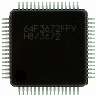
HD64F3672FPV Renesas Electronics America, HD64F3672FPV Datasheet - Page 113

HD64F3672FPV
Manufacturer Part Number
HD64F3672FPV
Description
IC H8/3672 MCU FLASH 64LQFP
Manufacturer
Renesas Electronics America
Series
H8® H8/300H Tinyr
Datasheets
1.DF36912GFHV.pdf
(277 pages)
2.DF36012GFYV.pdf
(1021 pages)
3.HD64F3672FXV.pdf
(334 pages)
Specifications of HD64F3672FPV
Core Processor
H8/300H
Core Size
16-Bit
Speed
16MHz
Connectivity
SCI
Peripherals
PWM, WDT
Number Of I /o
26
Program Memory Size
16KB (16K x 8)
Program Memory Type
FLASH
Ram Size
2K x 8
Voltage - Supply (vcc/vdd)
3 V ~ 5.5 V
Data Converters
A/D 4x10b
Oscillator Type
Internal
Operating Temperature
-20°C ~ 75°C
Package / Case
64-LQFP
For Use With
R0K436079S000BE - KIT DEV FOR H8/36079 W/COMPILER
Lead Free Status / RoHS Status
Lead free / RoHS Compliant
Eeprom Size
-
Available stocks
Company
Part Number
Manufacturer
Quantity
Price
Company:
Part Number:
HD64F3672FPV
Manufacturer:
MICROCHIP
Quantity:
1 000
Company:
Part Number:
HD64F3672FPV
Manufacturer:
Renesas Electronics America
Quantity:
135
Company:
Part Number:
HD64F3672FPV
Manufacturer:
Renesas Electronics America
Quantity:
10 000
Part Number:
HD64F3672FPV
Manufacturer:
RENESAS/瑞萨
Quantity:
20 000
- Current page: 113 of 277
- Download datasheet (2Mb)
2.2.28 (1) EEPMOV (B)
Notes
This instruction first reads the memory locations indicated by ER5 and ER6, then performs the
data transfer. The number of states required for execution differs from the H8/300 CPU.
EEPMOV (MOVe data to EEPROM)
Operation
if R4L
else next;
Assembly-Language Format
EEPMOV.B
Operand Size
—
Description
This instruction performs a block memory transfer. It moves data from the memory location
specified in ER5 to the memory location specified in ER6, increments ER5 and ER6, decrements
R4L, and repeats these operations until R4L reaches zero. Execution then proceeds to the next
instruction. No interrupts are detected while the block transfer is in progress. When the EEPMOV
instruction ends, R4L contains 0, and ER5 and ER6 contain the last transfer address + 1. The data
transfer is performed a byte at a time, with R4L indicating the number of bytes to be transferred.
The byte symbol in the assembly-language format designates the size of R4L (and limits the
maximum number of bytes that can be transferred to 255).
Operand Format and Number of States Required for Execution
Note: * n is the initial value of R4L. Although n bytes of data are transferred, memory is accessed 2(n + 1)
Addressing
Mode
repeat
until R4L = 0
—
times, requiring 4(n + 1) states. (n = 0, 1, 2, …, 255).
0 then
EEPMOV.B
Mnemonic
@ER5+
R4L – 1
@ER6+
R4L
Operands
1st byte
7
B
Condition Code
H: Previous value remains unchanged.
N: Previous value remains unchanged.
Z: Previous value remains unchanged.
V: Previous value remains unchanged.
C: Previous value remains unchanged.
2nd byte
5
Instruction Format
— —
I
Rev. 3.00 Dec 13, 2004 page 97 of 258
C
UI
Section 2 Instruction Descriptions
— —
H
3rd byte
5
U
9
Block Data Transfer
—
N
4th byte
8
REJ09B0213-0300
—
Z
F
—
V
States
No. of
8+4n *
—
C
Related parts for HD64F3672FPV
Image
Part Number
Description
Manufacturer
Datasheet
Request
R

Part Number:
Description:
KIT STARTER FOR M16C/29
Manufacturer:
Renesas Electronics America
Datasheet:

Part Number:
Description:
KIT STARTER FOR R8C/2D
Manufacturer:
Renesas Electronics America
Datasheet:

Part Number:
Description:
R0K33062P STARTER KIT
Manufacturer:
Renesas Electronics America
Datasheet:

Part Number:
Description:
KIT STARTER FOR R8C/23 E8A
Manufacturer:
Renesas Electronics America
Datasheet:

Part Number:
Description:
KIT STARTER FOR R8C/25
Manufacturer:
Renesas Electronics America
Datasheet:

Part Number:
Description:
KIT STARTER H8S2456 SHARPE DSPLY
Manufacturer:
Renesas Electronics America
Datasheet:

Part Number:
Description:
KIT STARTER FOR R8C38C
Manufacturer:
Renesas Electronics America
Datasheet:

Part Number:
Description:
KIT STARTER FOR R8C35C
Manufacturer:
Renesas Electronics America
Datasheet:

Part Number:
Description:
KIT STARTER FOR R8CL3AC+LCD APPS
Manufacturer:
Renesas Electronics America
Datasheet:

Part Number:
Description:
KIT STARTER FOR RX610
Manufacturer:
Renesas Electronics America
Datasheet:

Part Number:
Description:
KIT STARTER FOR R32C/118
Manufacturer:
Renesas Electronics America
Datasheet:

Part Number:
Description:
KIT DEV RSK-R8C/26-29
Manufacturer:
Renesas Electronics America
Datasheet:

Part Number:
Description:
KIT STARTER FOR SH7124
Manufacturer:
Renesas Electronics America
Datasheet:

Part Number:
Description:
KIT STARTER FOR H8SX/1622
Manufacturer:
Renesas Electronics America
Datasheet:


