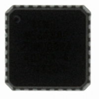
ATMEGA88P-20MU Atmel, ATMEGA88P-20MU Datasheet - Page 259

ATMEGA88P-20MU
Manufacturer Part Number
ATMEGA88P-20MU
Description
MCU AVR 8K ISP FLASH 20MHZ 32QFN
Manufacturer
Atmel
Series
AVR® ATmegar
Specifications of ATMEGA88P-20MU
Core Processor
AVR
Core Size
8-Bit
Speed
20MHz
Connectivity
I²C, SPI, UART/USART
Peripherals
Brown-out Detect/Reset, POR, PWM, WDT
Number Of I /o
23
Program Memory Size
8KB (4K x 16)
Program Memory Type
FLASH
Eeprom Size
512 x 8
Ram Size
1K x 8
Voltage - Supply (vcc/vdd)
2.7 V ~ 5.5 V
Data Converters
A/D 8x10b
Oscillator Type
Internal
Operating Temperature
-40°C ~ 85°C
Package / Case
32-VQFN Exposed Pad, 32-HVQFN, 32-SQFN, 32-DHVQFN
Processor Series
ATMEGA8x
Core
AVR8
Data Bus Width
8 bit
Data Ram Size
1 KB
Interface Type
I2C, SPI, USART
Maximum Clock Frequency
20 MHz
Number Of Programmable I/os
23
Number Of Timers
3
Maximum Operating Temperature
+ 85 C
Mounting Style
SMD/SMT
3rd Party Development Tools
EWAVR, EWAVR-BL
Development Tools By Supplier
ATAVRDRAGON, ATSTK500, ATSTK600, ATAVRISP2, ATAVRONEKIT, ATASTK512-EK1-IND
Minimum Operating Temperature
- 40 C
On-chip Adc
10 bit, 8 Channel
Package
32MLF
Device Core
AVR
Family Name
ATmega
Maximum Speed
20 MHz
Operating Supply Voltage
3.3|5 V
For Use With
ATAVRDRAGON - KIT DRAGON 32KB FLASH MEM AVRATAVRISP2 - PROGRAMMER AVR IN SYSTEM
Lead Free Status / RoHS Status
Lead free / RoHS Compliant
Available stocks
Company
Part Number
Manufacturer
Quantity
Price
Company:
Part Number:
ATMEGA88P-20MU
Manufacturer:
ATMEL
Quantity:
12 246
- Current page: 259 of 420
- Download datasheet (9Mb)
23.7
23.8
8025L–AVR–7/10
ADC Conversion Result
Temperature Measurement
After the conversion is complete (ADIF is high), the conversion result can be found in the ADC
Result Registers (ADCL, ADCH).
For single ended conversion, the result is
where V
Table 23-3 on page 260
0x3FF represents the selected reference voltage minus one LSB.
The temperature measurement is based on an on-chip temperature sensor that is coupled to a
single ended ADC8 channel. Selecting the ADC8 channel by writing the MUX3:0 bits in ADMUX
register to "1000" enables the temperature sensor. The internal 1.1V voltage reference must
also be selected for the ADC voltage reference source in the temperature sensor measurement.
When the temperature sensor is enabled, the ADC converter can be used in single conversion
mode to measure the voltage over the temperature sensor.
The measured voltage has a linear relationship to the temperature as described in
The voltage sensitivity is approximately 1 mV/°C and the accuracy of the temperature measure-
ment is +/- 10°C.
Table 23-2.
The values described in
temperature sensor output voltage varies from one chip to another. To be capable of achieving
more accurate results the temperature measurement can be calibrated in the application soft-
ware. The software calibration requires that a calibration value is measured and stored in a
register or EEPROM for each chip, as a part of the production test. The software calibration can
be done utilizing the formula:
where ADCn are the ADC data registers, k is a fixed coefficient and T
sor offset value determined and stored into EEPROM as a part of the production test.
Temperature / °C
Voltage / mV
IN
is the voltage on the selected input pin and V
Temperature vs. Sensor Output Voltage (Typical Case)
Table 23-2
and
T = { [(ADCH << 8) | ADCL] - T
Table 23-4 on page
242 mV
-45°C
are typical values. However, due to the process variation the
ADC
=
V
--------------------------
IN
V
⋅
REF
1024
261). 0x000 represents analog ground, and
ATmega48P/88P/168P
REF
314 mV
+25°C
the selected voltage reference (see
OS
} / k
OS
is the temperature sen-
380 mV
+85°C
Table
23-2.
259
Related parts for ATMEGA88P-20MU
Image
Part Number
Description
Manufacturer
Datasheet
Request
R

Part Number:
Description:
Manufacturer:
Atmel Corporation
Datasheet:

Part Number:
Description:
MCU AVR 8K ISP FLSH 20MHZ 32TQFP
Manufacturer:
Atmel
Datasheet:

Part Number:
Description:
MCU AVR 8K ISP FLASH 20MHZ 28DIP
Manufacturer:
Atmel
Datasheet:

Part Number:
Description:
MCU AVR 8KB FLASH 20MHZ 32TQFP
Manufacturer:
Atmel
Datasheet:

Part Number:
Description:
MCU AVR 8KB FLASH 20MHZ 32QFN
Manufacturer:
Atmel
Datasheet:

Part Number:
Description:
Atmega88p 8-bit Microcontroller With 8k Bytes In-system Programmable Flash
Manufacturer:
ATMEL Corporation
Datasheet:

Part Number:
Description:
IC MCU AVR 8K 5V 20MHZ 32-TQFP
Manufacturer:
Atmel
Datasheet:

Part Number:
Description:
Manufacturer:
Atmel Corporation
Datasheet:

Part Number:
Description:
Manufacturer:
Atmel Corporation
Datasheet:

Part Number:
Description:
MCU AVR 8K FLASH 15MHZ 32-QFN
Manufacturer:
Atmel
Datasheet:

Part Number:
Description:
IC AVR MCU 8K 20MHZ 5V 32TQFP
Manufacturer:
Atmel
Datasheet:

Part Number:
Description:
IC AVR MCU 8K 20MHZ 5V 32-QFN
Manufacturer:
Atmel
Datasheet:

Part Number:
Description:
IC AVR MCU 8K 20MHZ 5V 28DIP
Manufacturer:
Atmel
Datasheet:


