LP5952TL-1.5/NOPB National Semiconductor, LP5952TL-1.5/NOPB Datasheet - Page 13
LP5952TL-1.5/NOPB
Manufacturer Part Number
LP5952TL-1.5/NOPB
Description
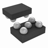
IC REG LDO 1.5V 350MA 5MICROSMD
Manufacturer
National Semiconductor
Series
PowerWise®r
Datasheet
1.LP5952TL-1.2EV.pdf
(16 pages)
Specifications of LP5952TL-1.5/NOPB
Regulator Topology
Positive Fixed
Voltage - Output
1.5V
Voltage - Input
Up to 4.5V
Voltage - Dropout (typical)
0.088V @ 350mA
Number Of Regulators
1
Current - Output
350mA
Operating Temperature
-40°C ~ 85°C
Mounting Type
Surface Mount
Package / Case
5-MicroSMD
For Use With
LP5952TL-1.5EV - BOARD EVALUATION LP5952TL-1.5
Lead Free Status / RoHS Status
Lead free / RoHS Compliant
Current - Limit (min)
-
Other names
LP5952TL-1.5TR
Available stocks
Company
Part Number
Manufacturer
Quantity
Price
Company:

Part Number:
LP5952TL-1.5/NOPB
Manufacturer:
Texas Instruments
Quantity:
10 000


ENABLE OPERATION
The LP5952 may be switched ON or OFF by a logic input at
the Enable pin, V
on. When the enable pin is low, the regulator output is off and
the device typically consumes 0.1µA.
If the application does not require the Enable switching fea-
ture, the V
output permanently on.
To ensure proper operation, the signal source used to drive
the V
specified turn-on/off voltage thresholds listed in the Electrical
Characteristics section under Enable Control Characteristics,
V
FAST TURN ON
Fast turn-on is guaranteed by an optimized architecture al-
lowing a fast ramp of the output voltage to reach the target
voltage while the inrush current is controlled low at 120mA
typical (for a C
SHORT-CIRCUIT PROTECTION
The LP5952 is short circuit protected and in the event of a
peak over-current condition, the output current through the
NFET pass device will be limited.
If the over-current condition exists for a longer time, the av-
erage power dissipation will increase depending on the input
to output voltage difference until the thermal shutdown cir-
cuitry will turn off the NFET.
Please refer to the section on thermal information for power
dissipation calculations.
THERMAL-OVERLOAD PROTECTION
Thermal-Overload Protection limits the total power dissipation
in the LP5952. When the junction temperature exceeds T
IL
and V
EN
input must be able to swing above and below the
IH
EN
.
pin should be tied to V
OUT
EN
of 2.2µF).
. A logic high at this pin will turn the device
BATT
to keep the regulator
J
=
13
165°C typ., the shutdown logic is triggered and the NFET is
turned off, allowing the device to cool down. After the junction
temperature dropped by 20°C (temperature hysteresis) typi-
cal, the NFET is activated again. This results in a pulsed
output voltage during continuous thermal-overload condi-
tions.
The Thermal-Overload Protection is designed to protect the
LP5952 in the event of a fault condition. For normal, continu-
ous operation, do not exceed the absolute maximum junction
temperature rating of T
Ratings).
REVERSE CURRENT PATH
The internal NFET pass device in LP5952 has an inherent
parasitic body diode. During normal operation, the input volt-
age is higher than the output voltage and the parasitic diode
is reverse biased. However, if the output is pulled above the
input in an application, then current flows from the output to
the input as the parasitic diode gets forward biased. The out-
put can be pulled above the input as long as the current in the
parasitic diode is limited to 50mA. For currents above this limit
an external Schottky diode must be connected from V
V
EVALUATION BOARDS
For availability of evaluation boards please refer to the Prod-
uct Folder of LP5952 at www.national.com.
For information regarding evaluation boards, please refer to
Application Note: AN-1531.
IN
(cathode on V
IN
, anode on V
J
= +150°C (see Absolute Maximum
OUT
).
www.national.com
OUT
to
Related parts for LP5952TL-1.5/NOPB
Image
Part Number
Description
Manufacturer
Datasheet
Request
R

Part Number:
Description:
IC REG LDO 1.2V 350MA MICRO5
Manufacturer:
National Semiconductor
Datasheet:
Part Number:
Description:
IC REG LDO 1.4V 350MA MICRO5
Manufacturer:
National Semiconductor
Datasheet:
Part Number:
Description:
IC REG LDO 1.6V 350MA MICRO5
Manufacturer:
National Semiconductor
Datasheet:
Part Number:
Description:
IC REG LDO 1.8V 350MA MICRO5
Manufacturer:
National Semiconductor
Datasheet:
Part Number:
Description:
IC REG LDO 1.3V 350MA 5MICROSMD
Manufacturer:
National Semiconductor
Datasheet:
Part Number:
Description:
IC REG LDO 0.7V 350MA 5MICROSMD
Manufacturer:
National Semiconductor
Datasheet:
Part Number:
Description:
IC REG LDO 2V 350MA 5MICROSMD
Manufacturer:
National Semiconductor
Datasheet:

Part Number:
Description:
IC REG LDO 350MA 1V 6-MSMD
Manufacturer:
National Semiconductor
Datasheet:
Part Number:
Description:
BOARD EVALUATION LP5952TL-1.2
Manufacturer:
National Semiconductor
Datasheet:
Part Number:
Description:
BOARD EVALUATION LP5952TL-1.3
Manufacturer:
National Semiconductor
Datasheet:
Part Number:
Description:
BOARD EVALUATION LP5952TL-1.5
Manufacturer:
National Semiconductor
Datasheet:
Part Number:
Description:
BOARD EVALUATION LP5952TL-1.8
Manufacturer:
National Semiconductor
Datasheet:

Part Number:
Description:
350mA Dual Rail Linear Regulator
Manufacturer:
NSC [National Semiconductor]
Datasheet:
Part Number:
Description:
National Semiconductor [8-Bit D/A Converter]
Manufacturer:
National Semiconductor
Datasheet:
Part Number:
Description:
National Semiconductor [Media Coprocessor]
Manufacturer:
National Semiconductor
Datasheet: