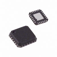
ADL5382ACPZ-R7 Analog Devices Inc, ADL5382ACPZ-R7 Datasheet - Page 16

ADL5382ACPZ-R7
Manufacturer Part Number
ADL5382ACPZ-R7
Description
IC DEMOD QUAD 700M2.7GHZ 24LFCSP
Manufacturer
Analog Devices Inc
Datasheet
1.ADL5382ACPZ-R7.pdf
(28 pages)
Specifications of ADL5382ACPZ-R7
Design Resources
Interfacing ADL5382 to AD9262 as an RF-to-Bits Solution (CN0062)
Function
Demodulator
Lo Frequency
700MHz ~ 2.7GHz
Rf Frequency
700MHz ~ 2.7GHz
P1db
14.5dBm
Gain
3.3dB
Noise Figure
17.6dB
Current - Supply
220mA
Voltage - Supply
4.75 V ~ 5.25 V
Package / Case
24-VFQFN, 24-CSP Exposed Pad
Frequency Range
700MHz To 2.7GHz
Rf Type
Quadrature
Supply Voltage Range
4.75V To 5.25V
Rf Ic Case Style
LFCSP
No. Of Pins
24
Operating Temperature Range
-40°C To +85°C
Lead Free Status / RoHS Status
Lead free / RoHS Compliant
Other names
ADL5382ACPZ-R7TR
Available stocks
Company
Part Number
Manufacturer
Quantity
Price
Company:
Part Number:
ADL5382ACPZ-R7
Manufacturer:
Analog Devices Inc
Quantity:
1 881
Part Number:
ADL5382ACPZ-R7
Manufacturer:
ADI/亚德诺
Quantity:
20 000
ADL5382
ERROR VECTOR MAGNITUDE (EVM) PERFORMANCE
EVM is a measure used to quantify the performance of a digital
radio transmitter or receiver. A signal received by a receiver
would have all constellation points at the ideal locations; however,
various imperfections in the implementation (such as magnitude
imbalance, noise floor, and phase imbalance) cause the actual
constellation points to deviate from the ideal locations.
The ADL5382 shows excellent EVM performance for various
modulation schemes. Figure 45 shows the EVM performance of
the ADL5382 with a 16 QAM, 200 kHz low IF.
Figure 46 shows the zero-IF EVM performance of a 10 MHz
IEEE 802.16e WiMAX signal through the ADL5382. The
differential dc offsets on the ADL5382 are in the order of a few
millivolts. However, ac coupling the baseband outputs with
10 μF capacitors eliminates dc offsets and enhances EVM
performance. With a 10 MHz BW signal, 10 μF ac coupling
capacitors with the 500 Ω differential load results in a high-pass
corner frequency of ~64 Hz, which absorbs an insignificant
amount of modulated signal energy from the baseband signal.
By using ac-coupling capacitors at the baseband outputs, the dc
offset effects, which can limit dynamic range at low input power
levels, can be eliminated.
–10
–15
–20
–25
–30
–35
–40
–45
–50
–5
0
–85
RF Input Power for a 16 QAM 160 ksym/s Signal
Figure 45. EVM, RF = 900 MHz, IF = 200 kHz vs.
–75
–65
RF INPUT POWER (dBm)
–55
–45
–35
–25
–15
–5
Rev. 0 | Page 16 of 28
Figure 47 exhibits multiple W-CDMA low-IF EVM
performance curves over a wide RF input power range into the
ADL5382. In the case of zero-IF, the noise contribution by the
vector signal analyzer becomes predominant at lower power
levels, making it difficult to measure SNR accurately.
Figure 47. EVM, RF = 1900 MHz, IF = 0 Hz, 2.5 MHz, 5 MHz, and 7.5 MHz vs. RF
10 MHz Bandwidth Mobile WiMAX Signal (AC-Coupled Baseband Outputs)
Figure 46. EVM, RF = 2.6 GHz, IF = 0 Hz vs. RF Input Power for a 16 QAM
Input Power for a W-CDMA Signal (AC-Coupled Baseband Outputs)
–10
–15
–20
–25
–30
–35
–40
–45
–50
–10
–15
–20
–25
–30
–35
–40
–45
–50
–5
–5
0
0
–65 –60 –55 –50 –45 –40 –35 –30 –25 –20 –15 –10 –5
–75 –70 –65 –60 –55 –50 –45 –40 –35 –30 –25 –20 –15 –10 –5
RF INPUT POWER (dBm)
RF INPUT POWER (dBm)
2.5MHz
0Hz
5MHz
7.5MHz
0
5
10


