AT42QT1070-SSU Atmel, AT42QT1070-SSU Datasheet - Page 40
AT42QT1070-SSU
Manufacturer Part Number
AT42QT1070-SSU
Description
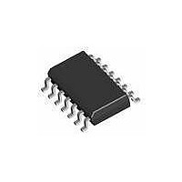
IC TOUCH SENSOR 7KEY 14-SOIC
Manufacturer
Atmel
Type
Capacitiver
Specifications of AT42QT1070-SSU
Number Of Inputs/keys
7 Key (Comms), 5 Key (Standalone)
Data Interface
I²C
Voltage Reference
Internal
Voltage - Supply
1.8 V ~ 5.5 V
Operating Temperature
-40°C ~ 85°C
Mounting Type
Surface Mount
Package / Case
14-SOIC (0.154", 3.90mm Width)
Supply Voltage
1.8 V to 5.5 V
Dimensions
3 mm L x 3 mm W x 0.8 mm H
Temperature Range
- 40 C to + 85 C
Termination Style
SMD/SMT
Lead Free Status / RoHS Status
Lead free / RoHS Compliant
Current - Supply
-
Resolution (bits)
-
Touch Panel Interface
-
Data Rate/sampling Rate (sps, Bps)
-
Lead Free Status / Rohs Status
Lead free / RoHS Compliant
Available stocks
Company
Part Number
Manufacturer
Quantity
Price
Company:

Part Number:
AT42QT1070-SSU
Manufacturer:
ATMEL
Quantity:
2 000
Company:
Part Number:
AT42QT1070-SSU QS529
Manufacturer:
Atmel
Quantity:
4 905


10620D–AT42–04/09
Mutual-capacitance Zero-dimensional Sensors
4.2.4.3
4-8
Avoiding False Key Detection
To avoid false keys, use any of the following tricks:
In addition, keep to the following general guidelines:
1. Watch out for time constants.
2. Behind from the point of view of touch.
Figure 4-9.a. 90° Crossing (Best)
Figure 4-9.c. X Under Ground Trace
Cross the X and Y traces as little as possible and then only at 90° (see
If the X and Y traces must run parallel to each other for a distance, separate the traces with a ground
trace. Where possible, use a ground trace that is twice as wide as the track-to-track gap
(see
Consider routing the X traces behind ground planes
traces is minimized, even if the Y traces run close to the X traces adjacent to the ground flood
(see
Route the Y traces completely behind
so they do not interact (see
Keep the X and Y traces thin where possible.
Route the Y traces farthest from touch where possible.
Generally, keep all the X traces together and all the Y traces together. This way the number of
potential false keys is substantially reduced.
Figure
Figure
Gaps are much bigger than a touch
Y
4-9.b).
4-9.c).
Y
X
X
Panel
Ground
Figure
Substrate
4-9.d).
(2)
the X traces if needed, or route the X and Y traces well apart
Figure 4-9.b. Separating ground Trace
Figure 4-9.d. Y Under X
(1)
. This means that the field between the X and Y
Y
Ground
Y
Figure
Touch Sensors Design Guide
Note:
Avoid long runs!
X
X
4-9.a).
Related parts for AT42QT1070-SSU
Image
Part Number
Description
Manufacturer
Datasheet
Request
R

Part Number:
Description:
DEV KIT FOR AVR/AVR32
Manufacturer:
Atmel
Datasheet:

Part Number:
Description:
INTERVAL AND WIPE/WASH WIPER CONTROL IC WITH DELAY
Manufacturer:
ATMEL Corporation
Datasheet:
Part Number:
Description:
Low-Voltage Voice-Switched IC for Hands-Free Operation
Manufacturer:
ATMEL Corporation
Datasheet:
Part Number:
Description:
MONOLITHIC INTEGRATED FEATUREPHONE CIRCUIT
Manufacturer:
ATMEL Corporation
Datasheet:
Part Number:
Description:
AM-FM Receiver IC U4255BM-M
Manufacturer:
ATMEL Corporation
Datasheet:
Part Number:
Description:
Monolithic Integrated Feature Phone Circuit
Manufacturer:
ATMEL Corporation
Datasheet:
Part Number:
Description:
Multistandard Video-IF and Quasi Parallel Sound Processing
Manufacturer:
ATMEL Corporation
Datasheet:
Part Number:
Description:
High-performance EE PLD
Manufacturer:
ATMEL Corporation
Datasheet:
Part Number:
Description:
8-bit Flash Microcontroller
Manufacturer:
ATMEL Corporation
Datasheet:
Part Number:
Description:
2-Wire Serial EEPROM
Manufacturer:
ATMEL Corporation
Datasheet: