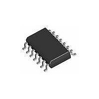
AT42QT1070-SSU Atmel, AT42QT1070-SSU Datasheet - Page 55

AT42QT1070-SSU
Manufacturer Part Number
AT42QT1070-SSU
Description
IC TOUCH SENSOR 7KEY 14-SOIC
Manufacturer
Atmel
Type
Capacitiver
Specifications of AT42QT1070-SSU
Number Of Inputs/keys
7 Key (Comms), 5 Key (Standalone)
Data Interface
I²C
Voltage Reference
Internal
Voltage - Supply
1.8 V ~ 5.5 V
Operating Temperature
-40°C ~ 85°C
Mounting Type
Surface Mount
Package / Case
14-SOIC (0.154", 3.90mm Width)
Supply Voltage
1.8 V to 5.5 V
Dimensions
3 mm L x 3 mm W x 0.8 mm H
Temperature Range
- 40 C to + 85 C
Termination Style
SMD/SMT
Lead Free Status / RoHS Status
Lead free / RoHS Compliant
Current - Supply
-
Resolution (bits)
-
Touch Panel Interface
-
Data Rate/sampling Rate (sps, Bps)
-
Lead Free Status / Rohs Status
Lead free / RoHS Compliant
Available stocks
Company
Part Number
Manufacturer
Quantity
Price
Company:
Part Number:
AT42QT1070-SSU
Manufacturer:
ATMEL
Quantity:
2 000
Company:
Part Number:
AT42QT1070-SSU QS529
Manufacturer:
Atmel
Quantity:
4 905
6.1
6.2
6.2.1
6.2.2
6.2.3
6.2.4
Touch Sensors Design Guide
Introduction
General Advice
QMatrix Channels
Ground Loading
Floating Conductive Items
Conductive Paints
This section describes how you design one-dimensional sensors using a mutual-capacitance
implementation (see
implement sliders or wheels for use with QMatrix sensor controllers.
As with self-capacitance one-dimensional sensors, two types of sensors can be considered: spatially
interpolated and resistively interpolated (see
Because QMatrix generally has fewer channel restrictions than QTouch, it is very common to make
sliders and wheels from 4 or more channels along a common Y line. In fact many chips are structured to
allow up to 8 channels for slider or wheel use.
One-layer sensors are quite resilient to ground loading in the same way as described in
“Ground Loading” on page
touch coordinate with moderate to high resolution, degrading SNR by introducing ground loading near
the sensor will directly compromise the resolution achievable. This can manifest itself as jitter in the
reported touch coordinate and is not desirable.
Flooded-X style sensors (see
particularly good at resisting ground loading from behind because the X drive is low impedance and so
can be “loaded” with very high amounts of parasitic capacitance before the RC time constant becomes a
concern.
Generally, the considerations of
The considerations for the use of floating conductive items described in
Conductive Items” on page 4-9
The considerations for the use of conductive paints described in
page 3-7
apply.
Mutual-capacitance One-dimensional Sensors
Section 1.2
4-6. However, with one-dimensional sensors that are designed to output a
apply.
Section 4.2.3 “Ground Loading” on page 4-6
Section 4.3.2 “Flooded-X Two-layer Method” on page
and
Section
Section 5.1 on page
1.3). These styles of sensors are typically used to
5-1).
Section 3.2.7 “Conductive Paints” on
still apply.
Section 4.2.6 “Floating
Section 6
10620D–AT42–04/09
Section 4.2.3
4-10) are
6-1


