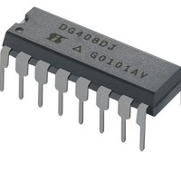
DG408LDY-E3 Vishay, DG408LDY-E3 Datasheet - Page 2

DG408LDY-E3
Manufacturer Part Number
DG408LDY-E3
Description
Multiplexer Switch ICs LV Single 8:1 3-bit Multiplexer/MUX
Manufacturer
Vishay
Type
Analog Multiplexerr
Specifications of DG408LDY-E3
Supply Current
0.2 mA
On Resistance (max)
80 Ohms
Propagation Delay Time
60 ns
On Time (max)
95 ns
Off Time (max)
100 ns
Supply Voltage (max)
12 V
Supply Voltage (min)
2.7 V
Maximum Power Dissipation
600 mW
Maximum Operating Temperature
+ 85 C
Minimum Operating Temperature
- 40 C
Package / Case
SOIC-16 Narrow
Mounting Style
SMD/SMT
Number Of Switches
Single
No. Of Circuits
1
On State Resistance Max
20ohm
Supply Voltage Range
3V To 6V
Operating Temperature Range
-40°C To +85°C
Analogue Switch Case Style
SOIC
No. Of Pins
16
Package
16SOIC N
Maximum On Resistance
80@2.7V Ohm
Maximum Propagation Delay Bus To Bus
60@12V|60@±5V|125@5V|150@3V ns
Maximum High Level Output Current
30 mA
Multiplexer Architecture
8:1
Maximum Turn-off Time
100@3V ns
Maximum Turn-on Time
95@3V ns
Power Supply Type
Single|Dual
Lead Free Status / RoHS Status
Lead free / RoHS Compliant
Lead Free Status / RoHS Status
Lead free / RoHS Compliant, Lead free / RoHS Compliant
DG408L/409L
Vishay Siliconix
For low and high voltage levels for V
ABSOLUTE MAXIMUM RATINGS
Voltage Referenced to V-
V+
GND
Digital Inputs
Current (Any Terminal)
Peak Current, S or D
(Pulsed at 1 ms, 10% Duty Cycle Max)
Storage Temperature: (A Suffix)
www.vishay.com
2
TRUTH TABLES AND ORDERING INFORMATION
*Block Diagram and Pin Configuration not shown.
. . . . . . . . . . . . . . . . . . . . . . . . . . . . . . . . . . . . . . . . . . . . . . . . . . . . . . . . . .
Temp Range
A
. . . . . . . . . . . . . . . . . . . . . . . . . . . . . . . . . . . . . . . . . . . . . . . . . . . . . . . . .
ORDERING INFORMATION
X
0
0
0
0
1
1
1
1
- 55 to 125_C
2
- 40 to 85_C
40 to 85_C
a
, V
TRUTH TABLE
S
, V
A
X
0
0
1
1
0
0
1
1
D
1
(D Suffix)
. . . . . . . . . . . . . . . . . . . . . .
. . . . . . . . . . . . . . . . . . . . . . . . . . . . . . . . . . . . . . .
. . . . . . . . . . . . . . . . . . . . . . . . .
A
. . . . . . . . . . . . . . . . . . . . . . . .
16-Pin TSSOP
16 Pin CerDIP
16-Pin CerDIP
X
0
1
0
1
0
1
0
1
16-Pin SOIC
Package
0
LCC-20*
. . . . . . . . . . . . . . . . . . . . . . . .
AX
DG408L
EN
0
1
1
1
1
1
1
1
1
(V- ) - 0.3 V to (V+) +0.3 V
and V
DG408LDY
DG408LDQ
DG408LAK
DG408LAK/883
DG408LAZ/883
Part Number
DG408L
EN
On Switch
consult “Digital Control” parameters for specific V+ operation.
- 65 to 150_C
- 65 to 125_C
None
1
2
3
4
5
6
7
8
100 mA
30 mA
14 V
7 V
Power Dissipation (Package)
16-Pin Plastic TSSOP
16-Pin Narrow SOIC
16-Pin CerDIP
LCC-20
Notes
a.
b.
c.
d.
e.
*Block Diagram and Pin Configuration not shown.
Temp Range
Signals on S
internal diodes. Limit forward diode current to maximum current ratings.
All leads soldered or welded to PC board.
Derate 7.6 mW/_C above 75_C.
Derate 12 mW/_C above 75_C.
Derate 10 mW/_C above 75_C.
ORDERING INFORMATION
A
- 55 to 125_C
e
X
0
0
1
1
- 40 to 85_C
1
40 to 85_C
. . . . . . . . . . . . . . . . . . . . . . . . . . . . . . . . . . . . . . . . . . . . . . . . .
d
TRUTH TABLE
. . . . . . . . . . . . . . . . . . . . . . . . . . . . . . . . . . . . . . . . . . .
X
, D
c
X,
c
. . . . . . . . . . . . . . . . . . . . . . . . . . . . . . . . . . . . . .
A
A
Logic “0”
Logic “1”
Logic “1”
X = Don’t Care
. . . . . . . . . . . . . . . . . . . . . . . . . . . . . . . . . . . .
X
x
0
1
0
1
, or EN exceeding V+ or V- will be clamped by
0
b
16-Pin TSSOP
16 Pin CerDIP
16-Pin CerDIP
16-Pin SOIC
Package
=
=
=
LCC-20*
V
V
V
EN
AL
AH
AH
0
1
1
1
1
v 0.8 V
w 2 4 V
w 2.4 V
DG409L
S-03720—Rev. D, 07-Apr-03
Document Number: 71342
DG409LDY
DG409LDQ
DG409LAK
DG409LAK/883
DG409LAZ/883
Part Number
On Switch
DG409L
None
1
2
3
4
650 mW
600 mW
900 mW
750 mW


