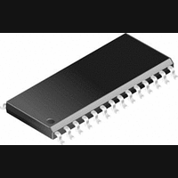
CS4228A-KSZ Cirrus Logic Inc, CS4228A-KSZ Datasheet - Page 27

CS4228A-KSZ
Manufacturer Part Number
CS4228A-KSZ
Description
IC, AUDIO CODEC, 24BIT, 100KHZ, SSOP-28
Manufacturer
Cirrus Logic Inc
Datasheet
1.CS4228A-KSZ.pdf
(30 pages)
Specifications of CS4228A-KSZ
Audio Codec Type
Stereo
No. Of Adcs
2
No. Of Dacs
6
No. Of Input Channels
2
No. Of Output Channels
6
Adc / Dac Resolution
24bit
Adcs / Dacs Signal To Noise Ratio
90dB
Lead Free Status / RoHS Status
Lead free / RoHS Compliant
Available stocks
Company
Part Number
Manufacturer
Quantity
Price
Part Number:
CS4228A-KSZ
Manufacturer:
CIRRUS
Quantity:
20 000
Mute Control - MUTEC
Differential Analog Inputs — AINR+, AINR- and AINL+, AINL-
Internal Voltage Filter - FILT
Analog Power - VA
Analog Ground - AGND
Analog Output - AOUT1, AOUT2, AOUT3, AOUT4, AOUT5 and AOUT6
DS307PP1
Pin 15, Output
Function:
Pins 16, 17 and 19, 20, Inputs
Function:
Pin 18, Output
Function:
Pin 21, Input
Function:
Pin 22, Input
Function:
Pins 23, 24, 25, 26, 27, 28, Outputs
Function:
The Mute Control pin goes low during the following conditions: power-up initialization, power-down, reset,
no master clock present, or if the master clock to left/right clock frequency ratio is incorrect. The Mute Con-
trol pin can also be user controlled by the MUTEC bit in the DAC Mute2 Control register. Mute Control can
be automatically asserted when 512 consecutive zeros are detected on all six DAC inputs, and automat-
ically deasserted when a single non-zero value is sent to any of the six DACs. The mute on zero function
is controlled by the MUTCZ bit in the DAC Mute2 Control register. The MUTEC pin is intended to be used
as a control for an external mute circuit to achieve a very low noise floor during periods when no audio is
present on the DAC outputs, and to prevent the clicks and pops that can occur in any single supply sys-
tem. Use of the Mute Control pin is not mandatory but recommended.
The analog signal inputs are presented deferentially to the modulators via the AINR+/- and AINL+/- pins.
The + and - input signals are 180° out of phase resulting in a nominal differential input voltage of twice the
input pin voltage. These pins are biased to the internal reference voltage of approximately 2.3 V. A pas-
sive anti-aliasing filter is required for best performance, as shown in Figure 5. The inputs can be driven at
-1dB FS single-ended if the unused input is connected to ground through a large value capacitor. A single
ended to differential converter circuit can also be used for slightly better performance.
Filter for internal circuits. An external capacitor is required from FILT to analog ground, as shown in Figure
5. FILT is not intended to supply external current. FILT+ has a typical source impedance of 250 k and
any current drawn from this pin will alter device performance. Care should be taken during board layout
to keep dynamic signal traces away from this pin.
Power for the analog and reference circuits. Typically 5.0 VDC.
Analog ground reference.
Analog outputs from the DACs. The full scale analog output level is specified in the Analog Characteristics
specifications table. The amplitude of the outputs is controlled by the Digital Volume Control registers
VOL6 - VOL1.
CS4228
27


