LM4950TS National Semiconductor, LM4950TS Datasheet - Page 19
LM4950TS
Manufacturer Part Number
LM4950TS
Description
Audio Power Amplifier IC
Manufacturer
National Semiconductor
Datasheet
1.LM4950TS.pdf
(25 pages)
Specifications of LM4950TS
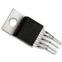
Amplifier Case Style
TO-220
No. Of Pins
9
Peak Reflow Compatible (260 C)
No
Termination Type
Through Hole
Leaded Process Compatible
No
Package / Case
9-TO-220
Operational Class
Class-AB
Audio Amplifier Function
Speaker
Input Offset Voltage
30@12VmV
Total Harmonic Distortion
0.05@4Ohm@2.5W%
Single Supply Voltage (typ)
12/15V
Dual Supply Voltage (typ)
Not RequiredV
Power Supply Requirement
Single
Rail/rail I/o Type
No
Power Supply Rejection Ratio
70dB
Single Supply Voltage (min)
9.6V
Single Supply Voltage (max)
16V
Dual Supply Voltage (min)
Not RequiredV
Dual Supply Voltage (max)
Not RequiredV
Operating Temp Range
-40C to 85C
Operating Temperature Classification
Industrial
Mounting
Surface Mount
Pin Count
9 +Tab
Package Type
TO-263
Lead Free Status / RoHS Status
Contains lead / RoHS non-compliant
Lead Free Status / RoHS Status
Contains lead / RoHS non-compliant
Available stocks
Company
Part Number
Manufacturer
Quantity
Price

Part Number:
LM4950TS
Manufacturer:
NS/国半
Quantity:
20 000
Company:
Part Number:
LM4950TSX
Manufacturer:
INTEL
Quantity:
182
Part Number:
LM4950TSX
Manufacturer:
NS/国半
Quantity:
20 000


Application Information
and an
As mentioned in the SELECTING EXTERNAL COMPO-
NENTS section, R
sets the amplifier’s lower bandpass frequency limit. Find the
coupling capacitor’s value using Equation (14).
The result is
Use a 0.82µF capacitor, the closest standard value.
The product of the desired high frequency cutoff (100kHz in
this example) and the differential gain A
Demonstration Board Layout
1 / (2πx20kΩx10Hz) = 0.795µF
f
L
INA
= 20kHz x 5 = 100kHz
C
and C
i
= 1 / 2πR
INA
create a highpass filter that
IN
f
L
FIGURE 5. Recommended TS SE PCB Layout:
VD
(Continued)
, determines the
Top Silkscreen
(13)
(14)
19
upper passband response limit. With A
100kHz, the closed-loop gain bandwidth product (GBWP) is
700kHz. This is less than the LM4950’s 3.5MHz GBWP. With
this margin, the amplifier can be used in designs that require
more differential gain while avoiding performance restricting
bandwidth limitations.
RECOMMENDED PRINTED CIRCUIT BOARD LAYOUT
Figure 5 through Figure 7 show the recommended two-layer
PC board layout that is optimized for the TO263-packaged,
SE-configured LM4950 and associated external compo-
nents. Figure 8 through Figure 10 show the recommended
two-layer PC board layout that is optimized for the TO263-
packaged, BTL-configured LM4950 and associated external
components. These circuits are designed for use with an
external 12V supply and 4Ω(min)(SE) or 8Ω(min)(BTL)
speakers.
These circuit boards are easy to use. Apply 12V and ground
to the board’s V
speaker between the board’s OUT
DD
and GND pads, respectively. Connect a
20047063
A
and OUT
VD
= 7 and f
B
outputs.
www.national.com
H
=
Related parts for LM4950TS
Image
Part Number
Description
Manufacturer
Datasheet
Request
R

Part Number:
Description:
National Semiconductor [8-Bit D/A Converter]
Manufacturer:
National Semiconductor
Datasheet:
Part Number:
Description:
National Semiconductor [Media Coprocessor]
Manufacturer:
National Semiconductor
Datasheet:
Part Number:
Description:
Digitally Controlled Tone and Volume Circuit with Stereo Audio Power Amplifier, Microphone Preamp Stage and National 3D Sound
Manufacturer:
National Semiconductor
Datasheet:
Part Number:
Description:
Digitally Controlled Tone and Volume Circuit with Stereo Audio Power Amplifier, Microphone Preamp Stage and National 3D Sound
Manufacturer:
National Semiconductor
Datasheet:
Part Number:
Description:
AC97 Rev 2 Codec with Sample Rate Conversion and National 3D Sound
Manufacturer:
National Semiconductor
Part Number:
Description:
Manufacturer:
National Semiconductor
Datasheet:
Part Number:
Description:
Manufacturer:
National Semiconductor
Datasheet:
Part Number:
Description:
General Purpose, Low Voltage, Low Power, Rail-to-Rail Output Operational Amplifiers
Manufacturer:
National Semiconductor
Datasheet:
Part Number:
Description:
8-bit 20 MSPS flash A/D converter.
Manufacturer:
National Semiconductor
Datasheet:
Part Number:
Description:
Low Noise Quad Operational Amplifier
Manufacturer:
National Semiconductor
Datasheet:
Part Number:
Description:
Quad Differential Line Receivers
Manufacturer:
National Semiconductor
Datasheet:
Part Number:
Description:
Quad High Speed Trapezoidal? Bus Transceiver
Manufacturer:
National Semiconductor
Datasheet:
Part Number:
Description:
Dual Line Receiver
Manufacturer:
National Semiconductor
Datasheet:
Part Number:
Description:
TTL to 10k ECL Level Translator with Latch
Manufacturer:
National Semiconductor
Datasheet: