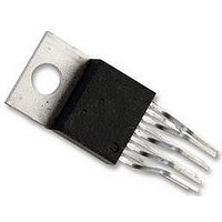
LM4950TS National Semiconductor, LM4950TS Datasheet - Page 4

LM4950TS
Manufacturer Part Number
LM4950TS
Description
Audio Power Amplifier IC
Manufacturer
National Semiconductor
Datasheet
1.LM4950TS.pdf
(25 pages)
Specifications of LM4950TS
Amplifier Case Style
TO-220
No. Of Pins
9
Peak Reflow Compatible (260 C)
No
Termination Type
Through Hole
Leaded Process Compatible
No
Package / Case
9-TO-220
Operational Class
Class-AB
Audio Amplifier Function
Speaker
Input Offset Voltage
30@12VmV
Total Harmonic Distortion
0.05@4Ohm@2.5W%
Single Supply Voltage (typ)
12/15V
Dual Supply Voltage (typ)
Not RequiredV
Power Supply Requirement
Single
Rail/rail I/o Type
No
Power Supply Rejection Ratio
70dB
Single Supply Voltage (min)
9.6V
Single Supply Voltage (max)
16V
Dual Supply Voltage (min)
Not RequiredV
Dual Supply Voltage (max)
Not RequiredV
Operating Temp Range
-40C to 85C
Operating Temperature Classification
Industrial
Mounting
Surface Mount
Pin Count
9 +Tab
Package Type
TO-263
Lead Free Status / RoHS Status
Contains lead / RoHS non-compliant
Lead Free Status / RoHS Status
Contains lead / RoHS non-compliant
Available stocks
Company
Part Number
Manufacturer
Quantity
Price
Part Number:
LM4950TS
Manufacturer:
NS/国半
Quantity:
20 000
Company:
Part Number:
LM4950TSX
Manufacturer:
INTEL
Quantity:
182
Part Number:
LM4950TSX
Manufacturer:
NS/国半
Quantity:
20 000
www.national.com
Electrical Characteristics V
Note 6: Typicals are measured at 25˚C and represent the parametric norm.
Note 7: Limits are guaranteed to National’s AOQL (Average Outgoing Quality Level).
Note 8: Datasheet min/max specification limits are guaranteed by design, test, or statistical analysis.
Note 9: Shutdown current is measured in a normal room environment. The Shutdown pin should be driven as close as possible to GND for minimum shutdown
current.
External Components Description
1. R
2. C
3. R
4. C
5. C
Components
IN
IN
F
S
BYPASS
This is the inverting input resistance that, along with R
and input capacitance C
This is the input coupling capacitor. It blocks DC voltage at the amplifier’s inverting input. C
create a highpass filter. The filter’s cutoff frequency is f
EXTERNAL COMPONENTS, for an explanation of determining C
This is the feedback resistance that, along with R
The supply bypass capacitor. Refer to the POWER SUPPLY BYPASSING section for information about
properly placing, and selecting the value of, this capacitor.
This capacitor filters the half-supply voltage present on the BYPASS pin. Refer to the Application section,
SELECTING EXTERNAL COMPONENTS, for information about properly placing, and selecting the
value of, this capacitor.
FIGURE 2. Typical Stereo Single-Ended (SE) Audio Amplifier Application Circuit
IN
DD
form a high pass filter. The filter’s cutoff frequency is f
= 12V
Refer to (Figure 1.)
Functional Description
(Notes 1, 2) (Continued)
4
i
, sets closed-loop gain.
F
C
, sets the closed-loop gain. Input resistance R
= 1/(2πR
IN
IN
’s value.
C
IN
). Refer to the SELECTING
c
= 1/(2πR
IN
IN
20047072
C
and R
IN
).
IN
IN


