D10DNFP BANNER ENGINEERING, D10DNFP Datasheet - Page 5
D10DNFP
Manufacturer Part Number
D10DNFP
Description
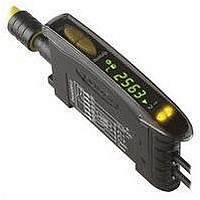
Photoelectric Sensor
Manufacturer
BANNER ENGINEERING
Type
Dual Discrete Outputr
Specifications of D10DNFP
Sensor Output
NPN
Sensor Input
Fiber Optic
Output Type
Transistor
Contact Current Max
150mA
Switch Terminals
Connector
Body Style
Rectangular
Brand/series
Expert™
Current, Switching
150 mA
Function
Fiber Optic
Indicator
LCD
Ip Rating
IP50
Material, Casing
Black ABS⁄Polycabonate Alloy (Housing)
Material, Cover
Polycarbonate
Mounting Type
DIN Rail
Output
NPN
Primary Type
Photoelectric
Sensing Mode
Selectable
Technology
Photoelectric
Temperature, Operating
-20 to +55 °C
Termination
Cable
Time, Response
50 μs, 200 μs, 1 ms, 2.5 ms
Voltage, Supply
24 VDC
Accessories Available
Cordsets and Plastic Fiber Optic Cable
Fiber Optic Sensor Type
Dual Discrete Output
Lead Free Status / Rohs Status
RoHS Exempt Product


Figure 5. Contrast Values
Figure 4. Dynamic TEACH (Light Operate
(no signal)
(no signal)
(no signal)
Darkest
Darkest
Darkest
100-500
Banner Engineering Corp.
32-99
500+
0-31
Darkest Taught
Output OFF
www.bannerengineering.com • Tel: 763.544.3164
Condition
Output OFF
Output OFF
shown)
between taught conditions
Contrast Values
Excellent: Very stable operation.
Good: Minor sensing variables will
not affect sensing reliability.
Low: Minor sensing variables may
affect sensing reliability.
Marginal: Consider an alternate
sensing scheme.
Sensing window size
• Press and hold
• Present Output
• Release Dynamic
threshold midway
Sensor positions
Dynamic (+)
button.
ON/OFF conditions
while continuing to
hold Dynamic button.
button.
Manual Adjust
Manual Adjust
Manual Adjust
adjusted by
adjusted by
adjusted by
Output ON
condition
Position
Position
sensing
Single
Push Button
•
Minneapolis, MN U.S.A.
Output ON
Output ON
Lightest Taught
Condition
Output OFF
Most Light
Most Light
Most Light
(saturated
(saturated
(saturated
signal)
signal)
signal)
T
T
T
T
• TEACH on-the-fly.
• Sets a single threshold.
• Threshold position is adjustable using the “+” and “-” buttons (see Manual Adjust, page 9).
Dynamic TEACH is used to program sensitivity during actual machine run conditions.
During Dynamic TEACH, the sensor takes multiple samples of the light and dark conditions
and automatically sets the sensitivity at the optimum level. Dynamic TEACH activates the
sensor’s adaptive threshold system, which continuously tracks minimum and maximum signal
levels, and automatically maintains centering of the switch point between the light and dark
conditions. The adaptive threshold system remains in effect during RUN mode to automatically
adjust for changes in the light or the dark conditions.
When Dynamic TEACH mode is used to program sensitivity, the output ON state (light or dark
operate) will remain as it was last programmed. To change to either light or dark operate, use
the SETUP mode (see page 10).
Dynamic TEACH and Manual Adjust
Sensitivity may be adjusted at any time when the sensor is in RUN mode by clicking the “+”
and “-” buttons. However, when a manual adjustment is made, the adaptive threshold system
is disabled (cancelled).
T
T
T
T
• Hold remote line
• Present Output
• Release remote
T
T
ON/OFF conditions
while continuing
to hold remote
line low (to ground)
low (to ground).
line/switch.
0.04 sec. ≤ T ≤ 0.8 sec.
T
T
Remote
Dynamic TEACH and Adaptive Thresholds
T
T
D10 Expert
T
T
T
T
T
T
T
T
T
T
T
T
• Display flashes “dyn”
• Arrow icon turns red
TEACH conditions acceptable:
• Display flashes “pass,” followed
• Sensor returns to RUN mode with
• Arrow icon turns green
TEACH conditions unacceptable:
• Display flashes “fail”
• Arrow icon remains red
• Sensor returns to RUN mode
by a number (denoting contrast);
see Figure 5.
new settings.
(Arrow icon turns green) without
changing settings.
™
T
T
Dual Discrete Outputs
T
T
Result
P/N 64154 rev. F
5
Related parts for D10DNFP
Image
Part Number
Description
Manufacturer
Datasheet
Request
R

Part Number:
Description:
Photoelectric Sensor
Manufacturer:
BANNER ENGINEERING
Datasheet:

Part Number:
Description:
Photoelectric Sensor
Manufacturer:
BANNER ENGINEERING
Datasheet:

Part Number:
Description:
LEDIR70XD4-XM-81039 MAX INTENS STROBE ONLY NO BANNER MARKS
Manufacturer:
BANNER ENGINEERING
Part Number:
Description:
M18SP6DL-72225 LABELED MOELLER NO BANNER MARKINGS BULK PACK
Manufacturer:
BANNER ENGINEERING
Part Number:
Description:
M18SP6DLQ-72226 LABLED MOELLER NO BANNER MARKINGS BULK PACK
Manufacturer:
BANNER ENGINEERING
Part Number:
Description:
M18SP6L-72223 LABELED MOELLER NO BANNER MARKINGS BULK PACK
Manufacturer:
BANNER ENGINEERING
Part Number:
Description:
M18SP6LQ-72224 LABELED MOELLER NO BANNER MARKINGS BULK PACK
Manufacturer:
BANNER ENGINEERING
Part Number:
Description:
P4D1-77908 P4 DRIVER GENERIC NO BANNER MARKINGS RESALE TO CUSTOMER
Manufacturer:
BANNER ENGINEERING
Part Number:
Description:
Photoelectric Sensor
Manufacturer:
BANNER ENGINEERING
Datasheet:

Part Number:
Description:
Programmable Indicator Light
Manufacturer:
BANNER ENGINEERING
Datasheet:
Part Number:
Description:
INDICATOR LED PANEL 50MM GRN/RED/YEL 30V
Manufacturer:
BANNER ENGINEERING
Datasheet:
Part Number:
Description:
Programmable Indicator Light
Manufacturer:
BANNER ENGINEERING
Datasheet: