S701G25N3S EATON CUTLER HAMMER, S701G25N3S Datasheet - Page 64
S701G25N3S
Manufacturer Part Number
S701G25N3S
Description
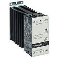
Motor Starter
Manufacturer
EATON CUTLER HAMMER
Datasheet
1.S701D03N3S.pdf
(90 pages)
Specifications of S701G25N3S
No. Of Phases
Three
Power Rating
20hp
Current Rating
25A
Peak Reflow Compatible (260 C)
No
Output Current
25A
Supply Voltage Max
600VAC
Control Voltage Max
300V
Leaded Process Compatible
No
Lead Free Status / RoHS Status
Contains lead / RoHS non-compliant


39
39
39
39
39
39
39
39
39
39
39
39
39
39
39
39
39
39
39
39
39
39
39
39
39
39
39
39
39
39
39.2
Monitoring Capabilities
The S811 has an impressive
array of system monitoring
capabilities that allows users
to access real time process
and diagnostic data. This data
can be viewed at the device
with the DIM or through a
communications network.
Data over a communications
network can provide valuable
insight into the condition of
the equipment and
processes. Maintenance and
Average Line Current
Provides the average of
the three-phase rms line
currents in amps, accurate
to within 2%. Current data
can be used to indicate
a need for maintenance.
Increased currents in a
fixed load application can
indicate a reduction in
system efficiencies and
performance, signifying
system maintenance is due.
Average Pole Current
Provides the average of
the three-phase rms pole
currents in amps, accurate to
within 2%. The pole current
is the current through the
Soft Starter. The line and
pole current will be identical
in inline applications, and
will differ in inside-the-delta
applications.
Average Line Current
as a % FLA
Provides the average rms line
current as a percentage of
the S811 FLA setting.
Three-Phase Line Currents
Provides three rms phase line
currents in amps, accurate
to within 2%. Imbalances
or changes in the relative
phase current to one another
can indicate anomalies in
the motor or electrical
distribution system.
64
Control Products Catalog CA08102001E—September 2010 www.eaton.com
Reduced Voltage Motor Starters
Solid-State Starters
production personnel can
monitor critical operational
and maintenance data from a
central control station that
can be located far away from
the production facility.
Process data can be
monitored to determine
system anomalies that may
indicate a need for preventive
maintenance or an impeding
failure. Adjustments made
through the communications
Three-Phase Pole Currents
Provides three rms phase
pole currents in amps,
accurate to within 2%. The
pole current is the current
through the soft starter.
The line and pole current
will be identical in in-line
applications, and will differ in
inside-the-delta applications.
Three-Phase Line Voltages
Provides the individual rms
three-phase line voltages.
Imbalances or changes in
|the relative phase voltage
to one another can indicate
anomalies in the motor or
electrical distribution system.
Voltage can be used to
monitor electrical distribution
system performance.
Warnings, alarms and
system actions to low or
high voltage conditions can
be implemented.
network can reduce costs by
minimizing the time traveling
to the location where the
motor controls are located.
When faults do occur, real
time fault data can assist
maintenance in trouble-
shooting and planning repair
resources. Remote reset
signals can be given to
tripped devices without the
need for manual intervention
by maintenance personnel.
Percent Thermal Memory
Provides the real time
calculated thermal memory
value. The S811 calculates
thermal memory value. A
100% value represents the
maximum safe internal
temperature of the motor.
When the thermal memory
value reaches 100%, an
overload trip will occur,
removing power to the
motor.
The thermal memory value
can be of great use in
determining an impending
overload trip condition. When
using a communications
network, alarms can be
implemented in the process
monitoring system warning
of an impending trip before
the trip occurs, halting the
process. Costly system
downtime can be avoided.
DC Control Voltage
Monitors level of the 24 Vdc
control voltage. Fluctuations
in control voltage can cause
component malfunction and
failure. System control
voltage data can be used to
implement warnings, alarms
and system actions to low or
high voltage conditions.
Pole Temperature
Increases in power pole
temperature are caused by
increases in ambient
temperature, start/stop times
and start duty cycles.
Changes in pole
temperatures represent a
change in system operating
conditions. Identifying
unexpected operating
conditions or changes can
prompt maintenance and
aid in process evaluation
activities.
PCB Device Temperature
An increase in printed circuit
board (device) temperature is
a strong indication of an
increase in ambient
temperature. High ambient
temperature operation can
be identified with the device
temperature data. Device
temperature increases can
be due to undersized
enclosures, failure of cooling
fans or blocked venting. High
operating temperatures will
reduce the life of all electrical
equipment in the enclosure.
Start Count
Start count data can be
used to monitor system
output, schedule preventative
maintenance, identify
system anomalies and
identify changes in
system operation.
Related parts for S701G25N3S
Image
Part Number
Description
Manufacturer
Datasheet
Request
R

Part Number:
Description:
HEATSINK CLIP ON UNFINISH TO-220
Manufacturer:
CTS Thermal Management Products

Part Number:
Description:
SUB FEED LUG BLOCK 150A CUTLER HAMMER TYPE BR LOADCENTER
Manufacturer:
EATON CUTLER HAMMER
Part Number:
Description:
Handle Tie Bar For (2) - 1 Pole Type BR Breakers
Manufacturer:
EATON CUTLER HAMMER
Part Number:
Description:
Type CL Breaker 25A/1Pole 120/240V 10K-Classified 1" Ckt Bkr
Manufacturer:
EATON CUTLER HAMMER